Table of Contents

Subscribe to Our Youtube Channel
Related Manuals for R.V.R. Elettronica VJ10000-TE


Summary of Contents for R.V.R. Elettronica VJ10000-TE
- Page 1 Data redazione: 25/07/03 R.V.R. Elettronica S.r.l. (BO) VJ10000-TE - R.F. Tube Amplifier TECHNICAL AND MAINTENANCE MANUAL VJ10000-TE (4CX12000) 10Kw Power Tetrode Amplifier 87.5 - 108 MHz Manufactured by R.V.R. Elettronica - Italy...
-
Page 2: Table Of Contents
Data redazione: 25/07/03 R.V.R. Elettronica S.r.l. (BO) VJ10000-TE - R.F. Tube Amplifier INDEX I - PRELIMINARY INSTRUCTIONS AND WARRANTY INFORMATION............4 II - TUBE WARRANTY INSTRUCTIONS........................6 III – SAFETY REGULAMENT! ............................ 8 CHAPTER 1..................................12 TX10000-TE GENERAL DESCRIPTION ........................12 1.1) TRANSMITTER DESCRIPTION ........................ - Page 3 Data redazione: 25/07/03 R.V.R. Elettronica S.r.l. (BO) VJ10000-TE - R.F. Tube Amplifier PICTURES FIG. 1 FRONT VIEW DESCRIPTION ........................... 23 FIG. 2 FRONT VIEW ..............................24 FIG. 3 REAR VIEW ..............................25 FIG. 4 TOP VIEW DESCRIPTION ..........................28 FIG. 5 PROTECTIONS CARD DESCRIPTION ....................
-
Page 4: I - Preliminary Instructions And Warranty Information
Data redazione: 25/07/03 R.V.R. Elettronica S.r.l. (BO) VJ10000-TE - R.F. Tube Amplifier I - PRELIMINARY INSTRUCTIONS AND WARRANTY INFORMATION Please observe safety precautions when handling this unit. This equipment contains dangerous currents and high voltages. This manual is written as a general guide for those having previous knowledge and experience with this kind of equipment. - Page 5 Data redazione: 25/07/03 R.V.R. Elettronica S.r.l. (BO) VJ10000-TE - R.F. Tube Amplifier To claim your rights under this warranty: Contact the dealer or distributor where you prchased the unit. Describe the problem and ask if he has an easy solution. Dealers and Distributors are supplied with all the information about problems that may occur and usually they can repair the unit quicker than what the manufacturer could do.
-
Page 6: Tube Warranty Instructions
Data redazione: 25/07/03 R.V.R. Elettronica S.r.l. (BO) VJ10000-TE - R.F. Tube Amplifier II - TUBE WARRANTY INSTRUCTIONS VARIAN POWER GRID PRODUCT LIMITED WARRANTY Varian products are warranted to be free from defects in workmanship and materials only. The warranty involves both calendar time and filament (or heather) operation time. Specifically involved are: time since the product was shipped from varian time since delivery to the user, and operation time. - Page 7 Data redazione: 25/07/03 R.V.R. Elettronica S.r.l. (BO) VJ10000-TE - R.F. Tube Amplifier A prorated credit is calculated as follows: Warranty (hours) - Use Time (hours) = % Credit Warranty (hours) Thus for failure Code N (3000 hours) if failure occurred after 600 hours and was found to be...
-
Page 8: Safety Regulament
R.V.R. ELETTRONICA s.p.a. shall not be responsible for injury or damage resulting from improper procedures or from the use of improperly trained or inexperienced personnel performing such tasks. - Page 9 Data redazione: 25/07/03 R.V.R. Elettronica S.r.l. (BO) VJ10000-TE - R.F. Tube Amplifier TREATMET OF ELECTRICAL SHOCK 1) If victim is not responsive follow the A-B-C's of basic life support. PLACE VICTIM FLAT ON HIS BACK ON A HARD SURFACE A) AIRWAY...
- Page 10 Data redazione: 25/07/03 R.V.R. Elettronica S.r.l. (BO) VJ10000-TE - R.F. Tube Amplifier FIRST-AID Personnel engaged in the installation, operation, maintenance or servicing of this equipment are urged to become familiar with first-aid theory and practices. The following information is not intended to be a complete first-aid procedure, it is brief and is only to be used as a reference.
- Page 11 Data redazione: 25/07/03 R.V.R. Elettronica S.r.l. (BO) VJ10000-TE - R.F. Tube Amplifier...
-
Page 12: Chapter 1
Data redazione: 25/07/03 R.V.R. Elettronica S.r.l. (BO) VJ10000-TE - R.F. Tube Amplifier CHAPTER 1 TX10000-TE GENERAL DESCRIPTION 1.1) TRANSMITTER DESCRIPTION The TX10000-TE/V1 is an FM broadcast transmitter working in the frequency band from 87.5 MHz to 108 MHz. The transmitter is composed of a modulator (mono or stereo) mod. - Page 13 Data redazione: 25/07/03 R.V.R. Elettronica S.r.l. (BO) VJ10000-TE - R.F. Tube Amplifier I) led indicators as memory of the protection interventions happened (yellow color); J) led indicator to indicate the voluntary protections service stand-by for short time for a final amplifier overload.
- Page 14 Data redazione: 25/07/03 R.V.R. Elettronica S.r.l. (BO) VJ10000-TE - R.F. Tube Amplifier TABLE A ELECTRICAL CHARACTERISTICS Power Supply 3-phase with neutral: 380-415V±15% 3-phase without neutral: 208-240V±15% Manins Voltage Frequency 50-60 Hz Frequency Range 87.5 - 108 MHz Tube 4CX12000A Electrical power consumption...
- Page 15 Data redazione: 25/07/03 R.V.R. Elettronica S.r.l. (BO) VJ10000-TE - R.F. Tube Amplifier TABLE B MECHANICAL AND ENVIROMENTAL CHARACTERISTICS Rack dimensions 565 mm (22.24") W 850 mm (33.46") D 1930 mm (75.98") H Working temperature from -5° to +45°C Maximum installation admissible max 95% to 45°C without condensing...
- Page 16 Data redazione: 25/07/03 R.V.R. Elettronica S.r.l. (BO) VJ10000-TE - R.F. Tube Amplifier TABLE D READABLE PARAMETERS ON THE FRONT METER PANEL Output forward power Output reflected power Tetrode anode current Tetrode screen grid current Tetrode anode voltage Tetrode filament voltage...
- Page 17 Data redazione: 25/07/03 R.V.R. Elettronica S.r.l. (BO) VJ10000-TE - R.F. Tube Amplifier TABLE E READABLE PARAMETERS ON THE FRONT METER PANEL Excessive output reflected power in antenna Tetrode anode overcurrent Tetrode screen grid overcurrent Tetrode control grid overcurent Final stage overtemperature...
- Page 18 Data redazione: 25/07/03 R.V.R. Elettronica S.r.l. (BO) VJ10000-TE - R.F. Tube Amplifier TABLE F PROJECT STRUCTURE SPECIFICATIONS Amplifier cavity of the tetrode final stage 1/4 tuned with capacitor output coupling. Grounded-grid configuration of the Final stage tetrode through by-pass capacitors.
-
Page 19: Chapter 2
VJ10000-TE - R.F. Tube Amplifier CHAPTER 2 ELECTRICAL DESCRIPTION INTRODUCTION This chapter describes, in detail, the operating theory of the VJ10000-TE. To aid understanding, the unit has been subdivided into modules (fig.1A), each of which is fully described below. CONSIDERATIONS ON WORKING PARAMETERS The tetrode transmitter is equipped with polarization circuit much versatile that allows to choise the working Class and the "circulation electrical angle". -
Page 20: Tube
Data redazione: 25/07/03 R.V.R. Elettronica S.r.l. (BO) VJ10000-TE - R.F. Tube Amplifier The limits that mustn't reach are: - Anode current = 3,6A - Control grid current G1 = 300mA - Screen grid current G2 = 300mA - Output reflected power = 750V with a continuos working of 10KW in antenna - Anode dissipated thermal power of tetrode >... - Page 21 Data redazione: 25/07/03 R.V.R. Elettronica S.r.l. (BO) VJ10000-TE - R.F. Tube Amplifier The socket is situated in the bottom section, into which the tube is inserted.
- Page 22 Data redazione: 25/07/03 R.V.R. Elettronica S.r.l. (BO) VJ10000-TE - R.F. Tube Amplifier TABLE G SPECIFICATION OF THE 4CX20000C TUBE Model 4CX12000A Anode dissipation 12000 W Grid dissipation 150 W Frequency for max. ratings (CW) 110 MHz Cooling Forced ventilation Filament voltage 6.50 V...
- Page 23 Data redazione: 25/07/03 R.V.R. Elettronica S.r.l. (BO) VJ10000-TE - R.F. Tube Amplifier FIG. 1 FRONT VIEW DESCRIPTION Mos-Fet Wideband amplifier, strip line technology, output power 1000W. Free Panel. Free Panel. F.M. exciter controlled by microprocessor, stability 2.5 ppm, 10khz steps, output power from 0 to 30W adjustable, with LCD graphic display.
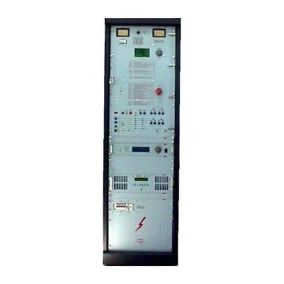
- Page 24 Data redazione: 25/07/03 R.V.R. Elettronica S.r.l. (BO) VJ10000-TE - R.F. Tube Amplifier FRONT VIEW...
- Page 25 Data redazione: 25/07/03 R.V.R. Elettronica S.r.l. (BO) VJ10000-TE - R.F. Tube Amplifier FIG. 2 REAR VIEW Rear cavity panel. Air filter panel. Pass-through power supply cables panel.
- Page 26 Data redazione: 25/07/03 R.V.R. Elettronica S.r.l. (BO) VJ10000-TE - R.F. Tube Amplifier Instruments rear Panel. FIG. 3 HINGED FRONTAL PANEL WITH TELEMETRY...
- Page 27 Data redazione: 25/07/03 R.V.R. Elettronica S.r.l. (BO) VJ10000-TE - R.F. Tube Amplifier REF. DESCRIPTION MULTIMETER: Analog instrument for the measures of temperature, filament voltage and current, anode voltage and current and grid voltage. VOLTAGES SELECTOR: Voltages selector for the measures of the following.
- Page 28 Data redazione: 25/07/03 R.V.R. Elettronica S.r.l. (BO) VJ10000-TE - R.F. Tube Amplifier FIG. 4 TOP VIEW DESCRIPTION FRONT PANELS REAR PANELS Out connectors. hot air outlet. 3"+1/8 R.F. output.
- Page 29 Data redazione: 25/07/03 R.V.R. Elettronica S.r.l. (BO) VJ10000-TE - R.F. Tube Amplifier FIG. 5 PROTECTIONS CARD DESCRIPTION Utilities protection switch. Working parameters measurement card. This card picks up all electrical measures of the power grid tube in order to send the requested signals toward the multimeter card, allarms box and remote control/telemetry.
- Page 30 Data redazione: 25/07/03 R.V.R. Elettronica S.r.l. (BO) VJ10000-TE - R.F. Tube Amplifier FIG. 6 R.F. CAVITY'S FRONT VIEW DESCRIPTION HIGT VOLTAGE SHORT CIRCUIT. VARIABLE CAPACITOR (MOVING SURFACE WITH FINGERS) KAPTON TEFLON RING TO PROTECT ELECTRIC ARC COLLAR FOR 4CX20000C TUBE...
- Page 31 Data redazione: 25/07/03 R.V.R. Elettronica S.r.l. (BO) VJ10000-TE - R.F. Tube Amplifier FIG. 7 WATTMETER VIEW DESCRIPTION LOW PASS FILTER. WATTMETER. 3-6) COVER THREAD BARS. AIR -FLOW CHIMNEY. TUNING MOTOR.
- Page 32 Data redazione: 25/07/03 R.V.R. Elettronica S.r.l. (BO) VJ10000-TE - R.F. Tube Amplifier FIG. 8 R.F. CAVITY LEFT SIDE VIEW DESCRIPTION LOW PASS FILTER. 3"+1/8 R.F. OUTPUT WITCH MOTOR LOAD. INPUT TUNING ADJUST -INPUT GRID ADJUST. VG1 INPUT VOLTAGE. VG2 INPUT VOLTAGE.
- Page 33 Data redazione: 25/07/03 R.V.R. Elettronica S.r.l. (BO) VJ10000-TE - R.F. Tube Amplifier FIG. 9 VOLTAGE STABILIZER DESCRIPTION ADJUSTABLE AUTOTRANSFORMER. SERVOMOTOR. CONTROL CIRCUIT. SOCKET. SERIES TRANSFORMER.
- Page 34 Data redazione: 25/07/03 R.V.R. Elettronica S.r.l. (BO) VJ10000-TE - R.F. Tube Amplifier FIG. 10 R.F. CAVITY'S REAR VIEW DESCRIPTION LOW PASS FILTER. 3"+1/8 OUTPUT. FILAMENT TRANSFORMER. PRESSURE SENSOR...
- Page 35 Data redazione: 25/07/03 R.V.R. Elettronica S.r.l. (BO) VJ10000-TE - R.F. Tube Amplifier FIG. 11 DETAIL REFERENCE CAPSCREW...
-
Page 36: Chapter 3
Remove the unit from its packing and, before anything else, ensure that the unit has not suffered any damage during transit and that all front panel controls are operational. 3.3 ASSEMBLY DESCRIPTION RECOMMENDED TOOLS FOR THE INSTALLATION OF VJ10000-TE N_ 1 Middle star screwdriver... -
Page 37: Transmitter Connection To Mains Voltage
Data redazione: 25/07/03 R.V.R. Elettronica S.r.l. (BO) VJ10000-TE - R.F. Tube Amplifier To mount this pipe is advisable to remove the micro switches before by the relative screws. The screws that must be used to fix this pipe are just mounted in the relative holes placed on the top of the cavity. -
Page 38: Tube Installation
Data redazione: 25/07/03 R.V.R. Elettronica S.r.l. (BO) VJ10000-TE - R.F. Tube Amplifier In case of DELTA configuration isn’t necessary the neutral connection while for STAR configuration the neutral connection is necessary too. The three phases connection cables must have minimum section of 25 mmq for a voltage of 380/415 V and must have minimum section of 35 mmq for a voltage of 208/240 V. -
Page 39: Tuning And Switch On Procedures
Data redazione: 25/07/03 R.V.R. Elettronica S.r.l. (BO) VJ10000-TE - R.F. Tube Amplifier Make sure that the contacts between pipe and tube, clamping verywell the clip placed on the bottom part of the tuning pipe (fig.9C). Then, clamp the other clip placed on the top of the tuning pipe. - Page 40 Data redazione: 25/07/03 R.V.R. Elettronica S.r.l. (BO) VJ10000-TE - R.F. Tube Amplifier Repeat this sequence of operations (increasing of the input power, correction of the input tuning for the minimum value of the reflected power on the driver, adjusting of the antenna coupling and final fine adjust of the tuning) until you have obtained the maximum programmed output power.
- Page 41 Data redazione: 25/07/03 R.V.R. Elettronica S.r.l. (BO) VJ10000-TE - R.F. Tube Amplifier FIG. 12 TUBE INSTALLATION DIAGRAM N°1 NOTE: SCREWS FOR REMOTION FRONT PANEL...
- Page 42 Data redazione: 25/07/03 R.V.R. Elettronica S.r.l. (BO) VJ10000-TE - R.F. Tube Amplifier FIG. 13 TUBE INSTALLATION DIAGRAM N°2 Plate pipe Grid Plate...
- Page 43 Data redazione: 25/07/03 R.V.R. Elettronica S.r.l. (BO) VJ10000-TE - R.F. Tube Amplifier REFERENCE WIEV VALVE INSTALLATION INTO CAVITY CHAMBER.
- Page 44 Data redazione: 25/07/03 R.V.R. Elettronica S.r.l. (BO) VJ10000-TE - R.F. Tube Amplifier FIG. 14 TUBE INSTALLATION DIAGRAM N°3 Plate pipe Grid Plate...
- Page 45 Data redazione: 25/07/03 R.V.R. Elettronica S.r.l. (BO) VJ10000-TE - R.F. Tube Amplifier CLOSE SCREWS PLATE VOLTAGE. BE SHURE TO INSERT CORRECTLY THE VALVE INTO CAVITY . REFERENCE WIEV OF CAPACITY LOAD...
-
Page 46: Chapter 4
Data redazione: 25/07/03 R.V.R. Elettronica S.r.l. (BO) VJ10000-TE - R.F. Tube Amplifier CHAPTER 4 MAINTENANCE 4.1 SAFETY REQUIREMENTS WARNING WARNING WARNING WARNING WARNING WARNING WARNING When the transmitter is operational, removing the rear panel will expose lethal voltages. Use insulated tools for all types of adjustment and do not touch any internal components when the unit is switched on. -
Page 47: Tube Replacement
Data redazione: 25/07/03 R.V.R. Elettronica S.r.l. (BO) VJ10000-TE - R.F. Tube Amplifier 4.4 TUBE REPLACEMENT Move the sliding panel to its upper limit (rods fully exposed), using the PLATE control. Disconnect the line supply from the unit. Ensure that the tube has cooled sufficiently to avoid severe burning. - Page 48 Data redazione: 25/07/03 R.V.R. Elettronica S.r.l. (BO) VJ10000-TE - R.F. Tube Amplifier FIG. 15 I/O RACK CONNECTORS I/O Rack Connectors. Reference View.
- Page 49 Data redazione: 25/07/03 R.V.R. Elettronica S.r.l. (BO) VJ10000-TE - R.F. Tube Amplifier FIG. 16 I/O RACK CONNECTORS...
- Page 50 Data redazione: 25/07/03 R.V.R. Elettronica S.r.l. (BO) VJ10000-TE - R.F. Tube Amplifier FIG. 17 REFERENCE VIEW...
- Page 51 Data redazione: 25/07/03 R.V.R. Elettronica S.r.l. (BO) VJ10000-TE - R.F. Tube Amplifier FIG. 18 R.F. CIRCUIT Circuit Diagram.
- Page 52 Data redazione: 25/07/03 R.V.R. Elettronica S.r.l. (BO) VJ10000-TE - R.F. Tube Amplifier FIG. 19 MEASURE CARD Circuit Diagram. Layout.
- Page 53 Data redazione: 25/07/03 R.V.R. Elettronica S.r.l. (BO) VJ10000-TE - R.F. Tube Amplifier FIG. 20 380V CIRCUIT Circuit Diagram.
- Page 54 Data redazione: 25/07/03 R.V.R. Elettronica S.r.l. (BO) VJ10000-TE - R.F. Tube Amplifier FIG. 21 LOW TENSION CIRCUIT Circuit Diagram. FIG. 22 MEASURE, ALLARMS, LOW-TENSION CIRCUIT Circuit Diagram.
- Page 55 Data redazione: 25/07/03 R.V.R. Elettronica S.r.l. (BO) VJ10000-TE - R.F. Tube Amplifier FIG. 23 POWER RELAY CARD Circuit Diagram. Reference View...
- Page 56 Data redazione: 25/07/03 R.V.R. Elettronica S.r.l. (BO) VJ10000-TE - R.F. Tube Amplifier FIG. 24 REFERENCES VIEW...
- Page 57 Data redazione: 25/07/03 R.V.R. Elettronica S.r.l. (BO) VJ10000-TE - R.F. Tube Amplifier FIG. 25 INTERFACE TELEMETRY CARD Circuit Diagram.
- Page 58 Data redazione: 25/07/03 R.V.R. Elettronica S.r.l. (BO) VJ10000-TE - R.F. Tube Amplifier FIG. 26 TUNINGS RELAY CARD Circuit Diagram. Reference View.
- Page 59 Data redazione: 25/07/03 R.V.R. Elettronica S.r.l. (BO) VJ10000-TE - R.F. Tube Amplifier FIG. 27 REFERENCES VIEW APPENDIX B CONSTRUCTION DETAILS AND COMPONENTS DESCRIPTION This appendix contains construction details, cables numeration and of some components description which composing the equipment.
- Page 60 Data redazione: 25/07/03 R.V.R. Elettronica S.r.l. (BO) VJ10000-TE - R.F. Tube Amplifier FIG. 28 POWER SUPPLY P1...
- Page 61 Data redazione: 25/07/03 R.V.R. Elettronica S.r.l. (BO) VJ10000-TE - R.F. Tube Amplifier FIG. 29 SECTIONAL VIEW OF THE POWER SUPPLY P1 SOCKET OF THE ANODE SUPPLY TRANSFORMER...
- Page 62 Data redazione: 25/07/03 R.V.R. Elettronica S.r.l. (BO) VJ10000-TE - R.F. Tube Amplifier FIG. 30 POWER SUPPLY P2...
- Page 63 Data redazione: 25/07/03 R.V.R. Elettronica S.r.l. (BO) VJ10000-TE - R.F. Tube Amplifier FIG. 31 SECTIONAL VIEW OF THE POWER SUPPLY P2 BLOWER FILAMENT TRANSFORMER RESISTORS INDUCTOR POWER SOCKET CAPACITOR...
- Page 64 Data redazione: 25/07/03 R.V.R. Elettronica S.r.l. (BO) VJ10000-TE - R.F. Tube Amplifier FIG. 32 PROTECTIONS PLANE...
- Page 65 Data redazione: 25/07/03 R.V.R. Elettronica S.r.l. (BO) VJ10000-TE - R.F. Tube Amplifier FIG. 33 REFERENCE VIEW...
- Page 66 Data redazione: 25/07/03 R.V.R. Elettronica S.r.l. (BO) VJ10000-TE - R.F. Tube Amplifier FIG. 34 RESISTORS PLANE...
- Page 67 Data redazione: 25/07/03 R.V.R. Elettronica S.r.l. (BO) VJ10000-TE - R.F. Tube Amplifier FIG. 35 RESISTORS PLANE...
- Page 68 Data redazione: 25/07/03 R.V.R. Elettronica S.r.l. (BO) VJ10000-TE - R.F. Tube Amplifier FIG. 36 REFERENCE VIEW...
- Page 69 Data redazione: 25/07/03 R.V.R. Elettronica S.r.l. (BO) VJ10000-TE - R.F. Tube Amplifier FIG. 37 TUNING MOTOR LOAD...
- Page 70 Data redazione: 25/07/03 R.V.R. Elettronica S.r.l. (BO) VJ10000-TE - R.F. Tube Amplifier FIG. 38 REFERENCE VIEW...
- Page 71 Data redazione: 25/07/03 R.V.R. Elettronica S.r.l. (BO) VJ10000-TE - R.F. Tube Amplifier FIG. 39 RHEOSTATS INTERNAL VIEW...
- Page 72 Data redazione: 25/07/03 R.V.R. Elettronica S.r.l. (BO) VJ10000-TE - R.F. Tube Amplifier FIG. 40 REFERENCE VIEW...
- Page 73 Data redazione: 25/07/03 R.V.R. Elettronica S.r.l. (BO) VJ10000-TE - R.F. Tube Amplifier FIG. 41 PJ1000 PROTECTION SWITCH - PROTECTION FUSES...
- Page 74 Data redazione: 25/07/03 R.V.R. Elettronica S.r.l. (BO) VJ10000-TE - R.F. Tube Amplifier FIG. 42 REFERENCE VIEW...
- Page 75 Data redazione: 25/07/03 R.V.R. Elettronica S.r.l. (BO) VJ10000-TE - R.F. Tube Amplifier FIG. 43 INPUT SOCKET...
- Page 76 Data redazione: 25/07/03 R.V.R. Elettronica S.r.l. (BO) VJ10000-TE - R.F. Tube Amplifier FIG. 44 REFERENCE VIEW...
- Page 77 Data redazione: 25/07/03 R.V.R. Elettronica S.r.l. (BO) VJ10000-TE - R.F. Tube Amplifier FIG. 45 UTILITIES SOCKET FIG. 46 REFERENCE VIEW...
- Page 78 Data redazione: 25/07/03 R.V.R. Elettronica S.r.l. (BO) VJ10000-TE - R.F. Tube Amplifier FIG. 47 HIGHT TENSION PANEL...
- Page 79 Data redazione: 25/07/03 R.V.R. Elettronica S.r.l. (BO) VJ10000-TE - R.F. Tube Amplifier Filament Transformer cable n° 116 (0V) in cable n° 113 (220) in cable HT out cable HT out Utilities Transformer cable n° 155 (0V) in cable n° 154 (220V) in cable n°...
- Page 80 Data redazione: 25/07/03 R.V.R. Elettronica S.r.l. (BO) VJ10000-TE - R.F. Tube Amplifier or by any information storage and retrieval system, without permission in writing from the publisher.
Need help?
Do you have a question about the VJ10000-TE and is the answer not in the manual?
Questions and answers