Table of Contents
Advertisement
Quick Links
Advertisement
Table of Contents

Related Manuals for AEG PSD18B-184X


Summary of Contents for AEG PSD18B-184X
- Page 2 mportant! It is essential that you read the instructions in this manual before assembling, operating and maintaining the product. Subject to technical modifications.
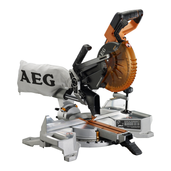
- Page 3 Ø 184 mm Ø 20 mm 40 HW 1.6 mm 7900 max. 1 - “D” Handle 2 - Head lock pin 3 - Blade wrench storage 4 - Single/dual bevel selector 5 - Bevel lock knob 6 - Sliding fence adjustment knob 7 - Switch trigger 8 - Lower guard lock out lever 9 - Upper blade guard...
- Page 4 Fig. 1 Fig. 3 1 - Mounting holes 1 - Sliding fence 2 - Mounting surface 2 - Slot 3 - Base 3 - Sliding fence adjustment knob Fig. 2 Fig. 4 1 - Work clamp Single/dual bevel selector 2 - Base 5 - Work clamp knob Bevel stop turret Fig.
- Page 5 Fig. 6 Fig. 8 1 - Mitre indicator screw 2 - Mitre scale indicator 3 - Mitre detent release button 4 - Mitre lock lever 5 - Mitre scale / Mitre scale detent plate Fig. 7 1 - Sliding fence 2 - Mitre detent release button 3 - Mitre lock lever 4 - Turning table...
- Page 6 Fig. 9 Fig. 11 Press the mitre detent release button to rotate the turning table. 1 - Mitre detent release button (press to disengage) 2 - Unlocked View of blade not square with fence, adjustments are required. Fig. 10 1 - Sliding fence 2 - Turning table 3 - Framing square 4 - Saw blade...
- Page 7 Fig. 13 Fig. 15 Correct view of blade square with turning table 1 - Saw blade 2 - Mitre lock lever 3 - Turning table 4 - Combination square Fig. 14 View of blade not square with turning table, adjustments are required.
- Page 8 Fig. 16 Fig. 17 Note: Before use, replace blade bolt cover screw and tighten securely to prevent guard movement. Note: Before use, replace blade bolt cover screw and tighten securely to prevent guard movement 1 - Depth control knob 2 - Depth stop Fig.
- Page 9 Fig. 19 Fig. 21 Shadow of blade teeth projected onto workpiece 1 - Push back Fig. 22 1 - LED button Fig. 20 Cross cut 1 - Slide cut 1 - Work clamp 2 - Slide saw arm forward, pull lower guard lock out lever 2 - Mitre detent release button to unlock lower guard, then push down.
- Page 10 Fig. 23 Fig. 25 33.9º 48º 45º Mitre cut 1 - Work clamp Fig. 24 Mitre cut 4 - Bevel stop turret 1 - Bevel lock knob 2 - Single/dual bevel selector 3 - Bevel stop adjustment screw Fig. 26 Bevel cut Compound mitre cut 1 - Work clamp...
- Page 11 Fig. 27 Fig. 30 52° 45° Ceiling Ceiling 38° 45° Wall Wall Top edge against fence: Left side, inside corner Right side, outside corner 1 - Long workpiece 2 - Workpiece supports Fig. 28 1 - Mitre fence 2 - Turning table 1 - Wide board Top edge against fence: Left side, inside corner...
- Page 12 Fig. 31 Fig. 34 Bottom edge against fence: Left side, inside corner Right side, outside corner Crown molding nested against front facing mitre fence Right 1 - Fixed fence 2 - Spring clamp (not included) 3 - Turning table Fig. 35 Fig.
- Page 13 Fig. 37 Unlock Lock 1 - Throat plates 2 - Mitre lock lever Fig. 38 1 - Throat plates 2 - Tensioning nut 3 - Lock nut...
-
Page 14: Replacement Parts
AL1218G L1840R L1850R L1860R Use AEG 18V battery and charger only. not use tools in damp or wet locations. Keep work area well lit. Do WARNING! Read all safety warnings and all instructions. Failure to follow Guard against electric shock. Avoid body contact with earthed or grounded surfaces (e.g. - Page 15 Use protective equipment. Use safety glasses. Use face or dust fatigue. Repairs should only be carried out by authorised service mask if working operations create dust. agents. Connect dust extraction equipment. If the tool is provided for Always use the guards on the machine. Do not use the machine if the guards are not in place and working correctly.
-
Page 16: Residual Risks
Always wear goggles and ear protection when using the machine. It is recommended to wear gloves, sturdy non-slip shoes and apron. The dual bevel slider mitre saw is to be used in dry conditions, with Before using any accessory, consult the instruction manual. The improper use of an accessory can cause damage and increase the The dual bevel slider mitre saw is intended for consumer use and potential for injury. -
Page 17: Blade Wrench
the saw arm to prevent sudden rise upon release of the tie wrap. WARNING Inspect the product carefully to make sure no breakage or Only use the lift handles on the table and/or the carrying handle damage occurred during shipping. on top to move or carry the product. -
Page 18: Operation
SQUARING THE SAW BLADE TO THE FENCE NOTE: saw blade, not the blade teeth. Rotate the blade by hand and check the blade-to-table Remove the battery pack from the product. alignment at several points. Pull the saw arm all the way down and lock in transport position. Lift the mitre lock lever to unlock the turning table. - Page 19 INSTALLING/REMOVING THE BATTERY PACK Wear gloves. Fit saw blade inside upper blade guard and onto spindle. The blade teeth point downward at the front of saw as shown in figure 16. Place the battery pack in the product. Align the raised rib on Replace the outer flange.
- Page 20 Before turning on the saw, perform a dry run of the cutting WARNING operation to make sure that no problems will occur when the cut is made. Never move the workpiece or make adjustment to any cutting angle while the saw is running and the blade is rotating. Any With the saw off, grasp the saw handle firmly then pull the saw slip can result in contact with the blade causing serious personal forward until the blade arbor (centre of the saw blade) is over...
- Page 21 lower guard. angle at the same time. This type of cut is used to make picture frames, cut molding, make boxes with sloping sides, and for certain Slowly lower the blade into and through the workpiece. roof framing cuts. Release the switch trigger and allow the saw blade to stop To make this type of cut the control arm on the turning table must rotating before raising the blade out of workpiece and removing be rotated to the correct angle and the saw arm must be tilted to...
- Page 22 CUTTING COMPOUND MITRES Number of sides Pitch of side M- 45.00° M- 36.00° M- 30.00° M- 25.71° M- 22.50° M- 20.00° M- 18.00° 0° B- 0.00° B- 0.00° B- 0.00° B- 0.00° B- 0.00° B- 0.00° B- 0.00° M- 44.89° M- 35.90°...
- Page 23 TO SUPPORT LONG WORKPIECES When setting the bevel and mitre angles for compound mitres, remember that the settings are interdependent; changing one angle changes the other angle as well. Long workpieces need extra supports. Supports should be placed Keep in mind that the angles for crown moldings are very precise along the workpiece so it does not sag.
- Page 24 lower guard. 33.9 (Right) Right side of outside corner 1. Bottom edge of molding against several seconds for the blade to reach maximum speed. fence Slowly lower the blade into and through the crown molding. 2. Turning table set right 31.6 Release the switch trigger and allow the saw blade to stop 3.
-
Page 25: Transportation And Storage
described in the Assembly section of this manual. turning table. If the mitre lock lever feels loose or the table moves easily when in the locked and unindexed position, an adjustment to If the blade is out of 45° bevel accuracy, adjust by tightening or loosening the bevel stop adjustment screw. -
Page 26: Maintenance
Use only AEG accessories and spare parts. Should components need to be replaced which have not been described, please contact one of our AEG service agents (see our list of guarantee/service addresses). If needed, an exploded view of the product can be ordered. Please state the Article No. - Page 28 Techtronic Industries GmbH Techtronic Industries (Australia) Pty. Ltd. Techtronic Industries N.Z. Limited Max-Eyth-Straße 10 31 Gilby Road, 2 Landing Drive, Mangere, 71364 Winnenden Mount Waverley VIC 3149, Auckland, New Zealand 2022 Germany Australia...
Need help?
Do you have a question about the PSD18B-184X and is the answer not in the manual?
Questions and answers