Huawei SmartAX MT880 User Manual
Hide thumbs
Also See for SmartAX MT880:
- User manual (47 pages) ,
- Quick installation manual (16 pages) ,
- Quick installation manual (14 pages)
Table of Contents
Advertisement
Quick Links
Advertisement
Table of Contents

Related Manuals for Huawei SmartAX MT880


Summary of Contents for Huawei SmartAX MT880
- Page 1 HUAWEI SmartAX MT880 ADSL Router User Manual V200R001...
- Page 2 Please feel free to contact our local office or company headquarters. Huawei Technologies Co., Ltd. Address: Administration Building, Huawei Technologies Co., Ltd., Bantian, Longgang District, Shenzhen, P. R. China Postal Code: 518129 Website: http://www.huawei.com...
- Page 3 Copyright © 2004 Huawei Technologies Co., Ltd. All Rights Reserved No part of this manual may be reproduced or transmitted in any form or by any means without prior written consent of Huawei Technologies Co., Ltd. Trademarks , HUAWEI, C&C08, EAST8000, HONET,...
- Page 4 About This Manual Release Notes The product version corresponds to the manual is SmartAX MT880 ADSL Router V200R001. Organization Chapter 1 provides a brief description of MT880 and a list of features. Chapter 2 introduces the hardware installation of MT880.
- Page 5 Installation engineers & technicians Operation & maintenance personnel Conventions The manual uses the following conventions: I. General conventions Convention Description Arial Normal paragraphs are in Arial. Warnings, C autions, N otes and Tips are in Arial Arial Narrow Narrow. Boldface Headings are in Boldface.
- Page 6 Environmental Protection This product has been designed to comply with the requirements on environmental protection. For the proper storage, use and disposal of this product, national laws and regulations must be observed.
-
Page 7: Table Of Contents
Table of Contents 1 MT880 Overview..............1-1 1.1 Appearance ..............1-1 1.2 Parts of MT880 ............. 1-1 1.2.1 Front Panel ............1-1 1.2.2 Rear Panel............1-2 1.2.3 External Splitter........... 1-3 1.3 MT880 Features ............1-4 2 Hardware Installation ............2-1 2.1 Preparations .............. - Page 8 4 Web-based Management............4-1 4.1 Manager Interface Layout ..........4-1 4.2 System View (Home Page) ..........4-3 4.3 WAN Setting ..............4-4 4.3.1 RFC2684 Bridged Connection ......4-4 4.3.2 RFC2684 Routed Configuration......4-8 4.3.3 PPP Configuration ..........4-10 4.4 DHCP Configuration ............ 4-12 4.5 DNS Configuration ............
- Page 9 5 Service Configuration ............5-1 5.1 Preparation for Service Configuration ......5-1 5.2 PPPoE Configuration............. 5-2 5.3 PPPoA Configuration............. 5-2 5.4 RFC 2684 Bridged (Pure Bridge) Configuration....5-3 5.5 RFC 2684 Bridged (Static IP) Configuration ....5-3 5.6 RFC 2684 Bridged (DHCP) Configuration ....... 5-4 5.7 RFC 2684 Route (IP oA) Configuration......
-
Page 10: Mt880 Overview
1 MT880 Overview In this chapter you will learn about the appearance and features of MT880. 1.1 Appearance MT880 provides the small and private network with simple, secure, and cost-efficient ADSL Internet connection. It enables many interactive multi-media applications such as the connection of video conferencing. -
Page 11: Rear Panel
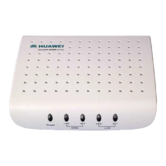
Figure 1-2 Front panel display with LED indicators The meanings of LEDs are listed as follows: LED Indicator Status Description Power Steady green light The unit is powered on. Steady green light A valid ADSL connection. ADSL LINK/ACT Blinking green light There is traffic over ADSL line. -
Page 12: External Splitter
Figure 1-3 Rear panel cable and power connections The meaning of ports and switch are listed as follows: Port & switch Description ADSL ADSL port, connecting to the splitter. Ethernet Ethernet port, connecting to PC or hub. Press this button for 3 seconds to restore the default setting. This Reset operation will let you lose your custom setting. -
Page 13: Mt880 Features
1.3 MT880 Features Data rates up to 24 Mbps for downstream and 1.2 Mbps for upstream Friendly Web-based graphical user interface configuration and management Supporting up to eight simultaneous virtual connections Widest range of DSLAM interoperability Built-in MIBs for SNMP management Upgradeable firmware through TFTP Easy to install and use... -
Page 14: Hardware Installation
2 Hardware Installation In this chapter you will learn about the various connections you need to make in order to use the MT880. Preparations Connecting MT880 Power on MT880 2.1 Preparations 2.1.1 Checking Computer Configuration Item Requirement Web browser, such as IE, is installed. Microsoft Internet Explorer ®... -
Page 15: Fixing Of Mt880
2.2 Fixing of MT880 MT880 enables horizontal and vertical positions as well as hanging on the wall. Place the MT880 in a location where the LED indicators can be easily viewed. 2.3 Connecting MT880 2.3.1 Connecting ADSL Line Simply plug one end of the twisted-pair telephone cable into the Modem port of the splitter and insert the other end into the ADSL port on the rear panel of MT880. -
Page 16: Connecting Ethernet Lan To Mt880
(1) Computer (2) RJ-11 Tel Cable (3) Phone (4) RJ-45 Ethernet Cable (5) Splitter (6) Phone Jack (7) MT880 (8) RJ-11 Tel Cable Figure 2-1 Computer to MT880 connection 2.3.3 Connecting Ethernet LAN to MT880 MT880 may be connected to any 10/100Base-TX Ethernet port. When connecting MT880 to any Ethernet device that is capable of operating at speeds higher than 10Mbps, be sure that the device has auto-negotiation mode enabled for the connecting port. -
Page 17: Powering On Mt880
2.4 Powering On MT880 Use the provided power adapter and plugs it into a suitable power source nearby. You should see the Power LED indicators light up, which indicates the device is powered on. After a few seconds, look at the LAN LINK indicator and make sure it with steady light, which indicates a valid connection between the Router and your computer. -
Page 18: Before Configuring Mt880
3 Before Configuring MT880 To configure MT880, you have to connect MT880 to a computer as shown below. Use the provided straight-through cable. (1) Computer (2) RJ-45 Ethernet Cable (3) MT880 Figure 3-1 Computer to MT880 Connection 3.1 When to Configure the MT880 The factory default settings of MT880 have optimized all functions, and made it can be operated in most conditions of network. -
Page 19: Configuring Ip Settings On Your Computer
should adjust accordingly the default settings to be able to adapt to the changes. 3.2 Configuring IP Settings on Your Computer The steps of configure the IP settings is as below. Understand the default IP settings for MT880: IP address (192.168.1.1), Subnet mask (255.255.255.0). -
Page 20: Checking For Proxy Service
3.3.1 Checking for Proxy Service If the browser software on the computer is configured to use a proxy server for Internet access, it is necessary to first disable the proxy connection. In Windows Internet Explorer, you can check whether a proxy server is enabled using the following procedures: Explorer Window,... - Page 21 Figure 3-2 Enter user name and password Use the default user name: admin and password: admin for first time setup. You can change the password once you have opened the Web-based configuration manager. The user name and password allows any computer on the same subnet as the MT880 to access the Web-based configuration manger.
-
Page 22: Web-Based Management
4 Web-based Management This chapter describes how to use the web-based management software to configure the MT880, which introduces the signification of parameters and method of setting in the configuration interface. The order of sectors is listed according to the functional configuration interfaces. - Page 23 Figure 4-1 GUI of Web-based Configuration Manager...
-
Page 24: System View (Home Page)
4.2 System View (Home Page) Figure 4-2 Home Page – System View Display The System View read-only table on the Home Page displays a summary of various system settings and functions as described below. -
Page 25: Wan Setting
ADSL Line Status: Displaying the ADSL State, Data Path, DSP version, Operation Mode, and the status of Upstream and Downstream for the A DSL line. WAN Channel: Displaying the names and settings for the device interfaces. Multiple software-defined interfaces may be configured to use the DSL connection. In the WAN interface will display the PVC number, gateway, IP address, mask, VPI/VCI, encapsulation and status. - Page 26 Encapsulation: You can select the mode LLC or VC MUX. Pure Bridge The setting page displayed as below will appear while you choose Pure Bridged mode. The gray item means it can be operated without any configuration. Figure 4-3 RFC2684 Bridged Connection-Application of Pure Bridge Static IP The setting page displayed as below will appear while you select Static IP setting mode.
- Page 27 Figure 4-4 RFC2684 Bridged Connection-application of Static IP IP Address and Subnet Mask: Entered IP address and subnet mask provided by ISP for the WAN interface of your MT880. Default Gateway: Enter the Gateway address provided by ISP. Default Route: This setting specified the IP address above is used for default route of LAN.
- Page 28 III. DHCP The setting page displayed as below will appear if you select DHCP mode, which means automatically acquire IP address from the DHCP sever of ISP. Figure 4-5 RFC2684 Bridged Connection-application of DHCP Default Route: This setting will automatically acquire IP address from the DHCP sever of ISP.
-
Page 29: Rfc2684 Routed Configuration
To save these configuration changes permanently, e nter the Tools>System Setting page, and click Save & Restart button to save new settings. 4.3.2 RFC2684 Routed Configuration Configuration page Figure 4-6 RFC2684 Routed (IPoA) Configuration Parameters eaplanation PVC: The system provides 7 PVCs. Generally you can leave this set at the default value 0. - Page 30 VPI: If you need any modification, please enter the VPI value provided by ISP. See the attached table for all the VPI default values of PVCs. VCI: If you need any modification, please enter the VCI value provided by ISP. See the attached table for all the VCI default values of PVCs.
-
Page 31: Ppp Configuration
4.3.3 PPP Configuration Configuration page Figure 4-7 PPP configuration Parameter explanation There are two options for PPP configuration: PPPoA and PPPoE. The parameters that need to be configured are described as below: 4-10... - Page 32 PVC: The system provides 7 PVCs. Generally you can leave this set at the default value 0. This option is also used to create and configure new PVCs. VPI: If you need any modification, please enter the VPI value provided by ISP. See the attached table for all the VPI default value of PVC.
-
Page 33: Dhcp Configuration
4.4 DHCP Configuration Click the DHCP of Home in the Wizard Column to set the DHCP configuration. MT880 can be set as DHCP server. Configuration page Figure 4-8 DHCP Configuration Parameter explanation DHCP Server: Choose ”Enable” to configure MT880 as DHCP server of LAN. -
Page 34: Dns Configuration
Starting/Ending IP Address: Enter the starting and ending IP address that will be provided DHCP service. Lease Time: Select the lease time from the drop-down menu. It will determine how long your PC can use the IP address provided by DHCP server. III. -
Page 35: Nat Configuration
Configuration page Figure 4-9 DNS Configuration Save Click the Apply button to save the settings in the RAM. To save these configuration changes permanently, e nter the Tools>System Setting page, and click Save & Restart button to save new settings. 4.6 NAT Configuration Network Address Translation is a method for disguising the private IP addresses on your LAN as the public IP address on the... - Page 36 selecting the Enabled or Disabled option in the configuration page and applying the settings. Configuration page Figure 4-10 NAT Configuration Parameter explanation The explanation of parameters in the above windows is as below. NAT: Select to enable or disable the NAT. The default is enabled.
-
Page 37: Static Route
III. Save Click the Apply button to save the settings in the RAM. To save these configuration changes permanently, enter the Tools>System Setting page, and click Save & Restart button to save new settings. 4.7 Static Route Click the Static Route of Home in the Wizard Column to set the static route for connection. -
Page 38: Lan Setting
Parameter explanation The explanation of parameters in the above windows is as below. Destination IP Address and Subnet Mask: Enter the destination IP address and subnet mask provided by ISP for the WAN interface of your MT880. Default Gateway: Enter the Gateway address provided by ISP. - Page 39 Configuration page Figure 4-12 LAN Configuration Parameter explanation IP Address: Type in the IP address for the Ethernet LAN interface. The default IP address is 192.168.1.1 Note: the public IP address that ISP assigned is not LAN IP address. The public IP address identifies the WAN interface that the ADSL Router connects to Internet.
-
Page 40: Virtual Server
To save these configuration changes permanently, enter the Tools>System Setting page, and click Save & Restart button to save new settings. & Note: If you change the IP address you need login again to access the web manager. 4.9 Virtual Server Click the Virtual Server of Advanced in the Wizard Column to set the virtual server. - Page 41 Configuration page Figure 4-13 Virtual Server Configuration Parameter explanation Status: Select to enable virtual server or not, the default is “Enabled”. Name: Enter the name of the virtual server to be added. Click Clear button to delete the entered server name. Private IP: Enter the IP address of local PC that provided the service of virtual server.
-
Page 42: Applications
Protocol Type: Select the protocol that to be applied. User can select a protocol from TCP and UDP, or both. Private Port: The port of local PC that to be applied to provide the service of virtual server. Public Port: The port that applied b y Internet user to access the LAN. - Page 43 Configuration page Figure 4-14 Special Application Configuration Parameter explanation Status: Select to enable or disable the applications, the default is “Enabled”. Name: Enter the name of the application to be added. Click Clear button to delete the entered name. Trigger Port: Enter the number of port, which to trigger the special application.
-
Page 44: Filters
Trigger Type: Select the protocol while the special applications to be triggered. Public Port: The port number of public network, which is used to access the special applications. User can specify a single port number or a group of port numbers. Using common to separate multiple port numbers. -
Page 45: Ip Filters
4.11.1 IP Filters Use IP Filters to deny particular LAN IP addresses to access the Internet. You can deny specific port numbers or all ports for a specific IP address. The well-known ports are displayed on the "IP filter list". Please click the edit icon to enable them. - Page 46 Parameter explanation Status: Select to enable or disable IP filter, the default is “Enabled”. Name: Enter a name for the rule, for easier identification later. Click Clear button to delete the entered name. Action: Select “Allow” to permit packets to pass through the MT880 if they meet the criteria of this rule, and “Deny”...
-
Page 47: Mac Filters
& Note: In the list, click icon to edit the relative IP filter rule. III. Save Click the Apply button to save the settings in the RAM. To save these configuration changes permanently, enter the Tools>System Setting page, and click Save & Restart button to save new settings. - Page 48 Configuration page Figure 4-16 MAC Filters Configuration Parameter explanation Status: Select to enable or disable IP filter, the default is “Enabled”. Name: Enter a name for the rule, for easier identification later. Click Clear button to delete the entered name. MAC Address: The MAC address of the computer on the LAN (Local Area Network) side.
-
Page 49: Url Blocking
computer's MAC address to the MAC Address section when the system detects the DHCP client automatically. III. Save Click the Apply button to save the settings in the RAM. To save these configuration changes permanently, e nter the Tools>System Setting page, and click Save & Restart button to save new settings. -
Page 50: Domain Blocking
Parameter explanation Status: Select to enable or disable IP filter, the default is “Enabled”. URL Address: Enter the URL that needed to be blocked. III. Save Click the Apply button to save the settings in the RAM. To save these configuration changes permanently, e nter the Tools>System Setting page, and click Save &... - Page 51 Configuration page Figure 4-18 Domain Blocking Configuration Parameter explanation Disabled Domain Blocking: Select to disable Domain Blocking. Allow: Select allow users to access all domains except "Blocked Domains" if you allow the users to access all domains except the domains on the Blocked Domains list. Deny: Select deny users to access all domains e xcept "Permitted Domains"...
-
Page 52: Firewall Rules
To save these configuration changes permanently, enter the Tools>System Setting page, and click Save & Restart button to save new settings. 4.12 Firewall Rules Click the Firewall Rules of Advanced in the Wizard Column to set the rules of firewall. The Firewall enables you to protect the system against denial of service (DoS) attacks and other types of malicious accesses to your LAN. - Page 53 Parameter explanation Blacklist Status: If you want the device to maintain and use a black list, click Enable. Click Disable if you do not want to maintain a list. Block Duration: Specifies the number of minutes that a computer's IP address will remain on the black list (i.e., all traffic originating from that computer will be blocked from passing through any interface on the MT880).
-
Page 54: Rip
being initiated; the state changes to active when packets are being exchanged, or closed when the exchange is complete. TCP connections in the open handshaking state can use up the available IP sessions. If the percentage is exceeded, then the open handshaking sessions will be closed and replaced with new sessions as they are initiated. - Page 55 Configuration page Figure 4-20 RIP Configuration RIP can be enabled on any existing WAN or LAN interfaces. It may be specified to receive RIP requests and reply to them, it can be specified to send RIP queries, or to both receive and send RIP packets.
-
Page 56: Administrator Setting
RIP 2 send: Select to enable or disable sending route information using RIP v2. Send MultiCast: Select to enable or disable sending route information using MultiCast. III. Save Click the Submit button to save the settings in the RAM. To save these configuration changes permanently, Tools>System Setting page, and click Save &... - Page 57 Configuration page Figure 4-21 Administrator Setting & Note: It is recommended to keep a record of the new password after modified. 4-36...
- Page 58 Parameter explanation Administrator Setting: To change the password used to access the MT880 web manager, Type the New Password and Confirm Password to be certain you have typed it correctly. Click the Apply button to activate the new password. Block WAN Ping: Pinging public WAN IP addresses is a common method used by hackers to test whether your WAN IP address is valid.
-
Page 59: Time
4.15 Time Click the Time of Tools in the Wizard Column to set the system time. The "system time" is used by the unit to synchronize scheduling services and system logging activities. You will need to set the time zone corresponding to your location. The time can be set manually or the device can connect to a NTP (Network Time Protocol) server to retrieve the time. -
Page 60: System Setting
4.16 System Setting Click the System Setting of Tools in the Wizard Column to configure the setting of system. Configuration page Figure 4-23 System Setting Parameter explanation Save: When clicking on Save, The current system settings can be saved as a file onto the local hard drive. The file will be saved as adslmodem.cfg. -
Page 61: Firmware Upgrade
Restore: The device can also be reset back to factory default settings by clicking Restore. Use the restore feature only if necessary. This will erase previously save settings for the unit. Save & Restart: You can save the new settings to permanent storage by clicking Save &... -
Page 62: Log
To upgrade the firmware, type in the name and path of the file or click the Browse button to search for the file. Click Apply button to begin copying the file. The file will load and restart the MT880 automatically. 4.18 Log Click the Log of Status in the Wizard Column to view the log of device. -
Page 63: Log Settings
Buttons Explanation First: The first page of the log. Last : The last page of the log. Previous: Moves back one log page. Next: Moves forward one log page. Clear: Clears the logs completely. Log Settings: Brings up the page to configure the logs. 4.18.2 Log Settings Not only does the device display the logs of activities and events, it can be setup to send these logs to another location. -
Page 64: Save
Buttons Explanation Server IP Status: Select to enable or disable sending the logs. SMTP Server: The address of the SMTP (Simple Mail Transfer Protocol) server that will be used to send the logs. Log Type: Select the type of activities that you want the ADSL Router to keep record. - Page 65 Figure 4-27 Diagnostics Window Select the Virtual Circuit and click the Submit button. A message will appear, informing you whether the loop test succeeded or failed. The diagnostics utility will run a series of test to check whether the device's connections are up and working. This takes only a few seconds.
-
Page 66: Traffic Statistics
4.20 Traffic Statistics Click the Traffic Statistics of Status in the Wizard Column to view the log of device. Figure 4-28 Traffic Statistics The device keeps statistic of the data traffic that it handles. You are able to read the amount of Receive and Transmit packets that pass through the device on both the WAN (Wide Area Network) port and the LAN (Local Area Network) ports. -
Page 67: Service Configuration
5 Service Configuration Following are six modes of the MT880 for ADSL online service: PPPoE PPPoA RFC 2684 Bridged (Pure Bridge) RFC 2684 Bridged (Static IP) RFC 2684 Bridged (DHCP) RFC 2684 Routed (IPoA) 5.1 Preparation for Service Configuration Collect the following data firstly to perform the configuration: Virtual dialup mode DSL mode PPPoE... -
Page 68: Pppoe Configuration
5.2 PPPoE Configuration Configurations on MT880 Location Parameters Comments Select any one from the eight PVCs. VPI/VCI The value shall be provided by your ISP. Operation Mode Select “Enable”. The value shall be provided by your ISP. Encapsulation Usually you can keep the default value:LLC. ATM Setting Connection Type Select “PPP”. -
Page 69: Rfc 2684 Bridged (Pure Bridge) Configuration
It is recommended to have DNS Relay function enabled. DHCP Mode It is recommended to have DHCP Server function enabled. Configurations on the user PC IP Address and It is recommended to set the mode as obtaining an IP address Network Mask automatically. -
Page 70: Rfc 2684 Bridged (Dhcp) Configuration
Configurations on MT880 Location Parameters Comments Gateway IP Address The value shall be provided by your ISP. It is recommended to enable the function of NAT. It is recommended to have DNS Relay function enabled. And set DNS IP address provided by your ISP. DHCP Mode It is recommended to have DHCP Server function enabled. -
Page 71: Rfc 2684 Route (Ipoa) Configuration
5.7 RFC 2684 Route (IPoA) Configuration Configurations on MT880 Location Parameters Comments Select any one from the eight PVCs. VPI/VCI The value shall be provided by your ISP. Operation Mode Select “Enable”. The value shall be provided by your ISP. Usually Encapsulation you can keep the default value:LLC. -
Page 72: Troubleshooting Guide
6 Troubleshooting Guide 6.1 Quick Troubleshooting Failures Instructions Power light is Ensure power adapter is well connected; out. Ensure the right power adapter is used. Ensure the ADSL line is well connected; Ensure the telephone line before entering the house is valid, try to test with a telephone;... -
Page 73: Faqs
6.2 FAQs Q: Why can’t my computer access the Internet, even when the physical links are well connected? Check first whether the LEDs are in normal status. If they do, you have to find help to adjust the settings on the MT880. Q: I forget the username and password when I am to log into the Web-based Configuration Manager. - Page 74 Q: Why does my PC fall off line sometimes even with all LEDs are in normal status? There are several scenarios might cause this problem. Be disconnected by the ISP. Some ISPs will have idle timeout setting to avoid wasting IP.
- Page 75 Q: How to connect multiple phones? Follow the figures below to complete the installation. Note that the MT880 needs the splitter for proper working. (1) Phone Socket (2~3) Phone (4) RJ-11 Tel Cable (5) Splitter (6~7) RJ-11 Tel Cable (8) Phone Jack (9) MT880 Figure 6-1 Connect Multiple Phones-1...
- Page 76 (1) Phone (2) Phone Socket (3) Phone (4) RJ-11 Tel Cable (5) Splitter (6) RJ-11 Tel Cable (7) Phone Socket (8) RJ-11 Tel Cable (9) Splitter (10) RJ-11 Tel Cable (11) Phone Jack (12) MT880 Figure 6-2 Connect Multiple Phones-2...
-
Page 77: Technical Specifications
7 Technical Specifications General Specifications ITU G.994.1 (G.hs) ITU G.992.5 Standards: ITU -T G.992.5 Annex L G.992.5 (ADSL2+): downstream rate of 24 Mbps, and upstream rate of 1.2 Mbps Data Transfer Rate: G.992.5 Annex L: Max. transmission distance of 6.5 kilometers One RJ-11 ports for ADSL line connection External Interface: One RJ-45 port for 10/100 Base-T Ethernet connection... -
Page 78: Appendix
8 Appendix 8.1 Fix MT880 into the Stand When in vertical position, the MT880 body should be assembled with the stand with the following steps. Before the installation, you have to notice that there is an L-shaped chip on the stand, which can be inserted into the wider slot on the back of MT880 body. -
Page 79: Factory Default Settings
Step 2 Have the L-shaped chips aligned with those positioning slots. Step 3 Push the body towards the stand. 8.2 Factory Default Settings User name admin Password admin IP address 192.168.1.1 Subnet mask 255.255.255.0 DSL Mode Multimode PVC0 RFC 2684 Bridged Mode VPI =0 VCI=35 PVC1 RFC 2684 Bridged Mode VPI =8... -
Page 80: Abbreviations
PVC6 RFC 2684 Bridged Mode VPI= 14 VCI=24 DHCP Mode Disable Enable (NAT session up to 1009) 8.3 Abbreviations ADSL Asymmetric Digital Subscriber Line Asynchronous Transfer Mode DHCP Dynamic Host Configuration Protocol Domain Name Server DSLAM Digital Subscriber Line Access Multiplex HTML Hypertext Markup Language Internet Protocols...
Need help?
Do you have a question about the SmartAX MT880 and is the answer not in the manual?
Questions and answers