Advertisement
Quick Links
Advertisement

Subscribe to Our Youtube Channel
Related Manuals for Caddytek incontro sports


Summary of Contents for Caddytek incontro sports
- Page 1 EZ Version 8 Push Buggy INSTRUCTIONAL MANUAL www.incontrosports.com.au / 03 5924 6056...
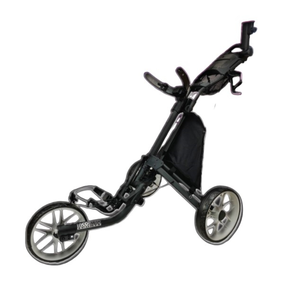
- Page 2 Parts Identification: Ergonomic Handle Umbrella Holder Umbrella Holder Base Scorecard holder assembly Umbrella Holder Storage Rack Handle Frame Upper Adjustable Bag Straps Handle Height Adjusting Knob Assembly Main Frame Front Connection Rod J1: Main Connection Rod Leg Frame Bracket Leg Frame L1: Leg Frame Leg Frame Lower Adjustable Bag Straps...
- Page 3 Assemble the Buggy Fig. 3 Fig. 2 Fig. 1 Handle Height Adjusting Knob button button Lift the upper bag holder Make sure the handle height Press the button on both bracket. adjusting knob is fully tightened. sides of the golf bag holder Pull the handle and upper bag mechanism to unfold the bag support wings automatically...
- Page 4 Folding button Folding The Buggy Fig. 8 Fig. 7 Fig. 9 button handle height adjusting knob Press the button and rotate Make sure the handle height adjusting knob is fully tightened .Slightly lift the front wheel 180 degree up the handle as Fig. 8 then press the folding button and push the handle counterclockwise so the front downward as shown in Fig.
-
Page 5: Umbrella Holder
Install The Drink Holder Fixed block on base notch Slot on drink holder Hole 1 Hole 2 Hole 2 Fig. 18 Fig. 17 Fig. 16 When installing the drink holder as Fig.16, align the smallest part of the slot on the holder with the fixed blocks. - Page 6 Optional Upper Bag Holder Strap When playing hilly golf course with steep downhill slopes or if the golf bag is an abnormal shape or size, this optional upper bag holder strap can help to further secure the golf bag and prevent the golf bag moving in the bag holder bracket. Fig.5 Fig.4 3.
-
Page 7: Front Wheel Alignment
Front Wheel Alignment Fig. Fig. 27 Fig. 28 bolt screws screws If the buggy veers to the right: Step 1: Face the front wheel of the buggy and use the provided Allen Key to loosen the two side screws as in fig. 27. Step 2: Then use the Allen Key to adjust the front bolt clockwise until the front wheel is centered as in Fig.
Need help?
Do you have a question about the incontro sports and is the answer not in the manual?
Questions and answers