Table of Contents
Advertisement
Quick Links
Advertisement
Table of Contents

Subscribe to Our Youtube Channel
Related Manuals for Schmidt SS 20.400


Summary of Contents for Schmidt SS 20.400
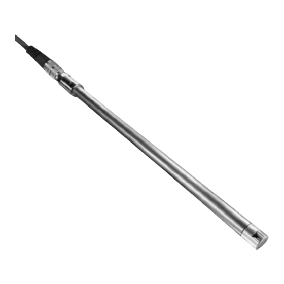
- Page 1 ® SCHMIDT Flow Sensor SS 20.400 Instructions for Use...
-
Page 2: Table Of Contents
® SCHMIDT Flow Sensor SS 20.400 Table of Contents Important Information ..............3 Application Range ................4 Mounting Instructions ..............5 Electrical Connection ..............10 Signalizing ..................15 Startup ................... 18 Information on Continuous Operation ........... 18 Service Information................ 19 Technical Data ................ -
Page 3: Important Information
2). In particular, it is not designed for direct or indirect protection of personal and machinery. SCHMIDT Technology cannot give any warranty as to its suitability for certain purpose and cannot be held liable for errors contained in these instructions for use or for accidental or sequential damage in connec- tion with the delivery, performance or use of this unit. -
Page 4: Application Range
2 Application Range ® The SCHMIDT Flow sensor SS 20.400 (article number: 518210) is de- signed for stationary use in clean rooms, air ducts or air shafts under at- mospheric pressure conditions and clean environmental conditions. The sensor measures flow velocity of the measuring medium as standard velocity (unit: m/s) relative to standard pressure of 1,013.25 hPa and... -
Page 5: Mounting Instructions
Commercially available welding stud (not included in delivery) must be welded. Countersunk head, not included in the delivery. Deviation between measuring direction of sensor head and flow direction. Instructions for Use – SCHMIDT ® Flow Sensor SS 20.400 Page 5... - Page 6 Tighten spigot nut by turning the fork wrench (AF17) by a quarter while maintaining the sensor in position. Threaded part 532160 Figure 3-1 The screw-in thread of the compression fitting must be sealed, e.g. with a teflon tape. Instructions for Use – SCHMIDT ® Flow Sensor SS 20.400 Page 6...
- Page 7 To reach the accuracy specified in its data sheets, the SS 20.400 has to be positioned in a straight conduit and at a place with undisturbed flow profile. An undisturbed flow profile can be achieved if a sufficiently long distance in front of the sensor (run-in distance) and behind the sensor (run-out distance) is held absolutely straight and without disturbances (such as edges, seams, bends, etc.).
- Page 8 Profile factor (for tubes with a circular cross section A) V Standard volumetric flow [m SCHMIDT Technology provides on its homepage a convenient calcula- tion tool to compute flow velocity or volume flow in pipes (circular or rec- tangle) for all its sensor types and measuring ranges: www.schmidt-sensors.com...
- Page 9 The wall mounting flange (520181) is designed for installation of the sen- sor SS 20.400 as an immersion sensor through a wall (e.g. wall of a flow box). The threaded bush included in the delivery has a base provided with a plane contact surface and two holes which allow a fast and easy instal- lation by means of two screws.
-
Page 10: Electrical Connection
4 Electrical Connection Plug-in connector The Flow Sensor SS 20.400 is equipped with a plug-in connector which is firmly integrated in the housing. The connector has the following data: Number of connection pins: 7 (plus shield connection on the metallic housing) - Page 11 The appropriate protection class III (SELV) respective PELV (EN 50178) has to be considered. Operating voltage The SS 20.400 is protected against a polarity reversal of the operating voltage. It has a nominal operating voltage range of U = 12 ... 26.4 V Only operate sensor in the defined operating voltage range (12 ...
- Page 12 The specific resistance of the lead of the nominal cable (0.14 mm at L = 10 m a current of I = 150 mA can cause a voltage drop up to 240 mV. B,max Instructions for Use – SCHMIDT ® Flow Sensor SS 20.400 Page 12...
- Page 13 ≈ 47 Ω ∙ I + 0.2 V Measuring resistor and switching transistor; additional leakage current of the TVS diode ≈ U connected in parallel (U ): < 100 µA S,max Instructions for Use – SCHMIDT ® Flow Sensor SS 20.400 Page 13...
- Page 14 30 V, negative impulses are short-circuited against GND (conducting-state voltage of a diode). Basic current of the switching transistor can be neglected. Transistor conducting Transient Voltage Suppressor diode Instructions for Use – SCHMIDT ® Flow Sensor SS 20.400 Page 14...
-
Page 15: Signalizing
5 Signalizing Analog output The following is valid for all output versions of the SS 20.400: Representation of measuring range: The measuring range of flow velocity (0 … w or |±w |) is N,max N,max mapped in a linear way to the signaling range of the used analog output type (see Table 4). - Page 16 Response time (damping of measured values): By default the response time of flow measurement is 1 s. Optionally it could be configured in the range of 0.01 … 10 s by order. Instructions for Use – SCHMIDT ® Flow Sensor SS 20.400...
- Page 17 (ordering). By default the middle of the positive measuring range is considered as the threshold value. Error signaling: Both switching outputs are conducting independent of their configured switching polarity. Instructions for Use – SCHMIDT ® Flow Sensor SS 20.400 Page 17...
-
Page 18: Startup
If the problems persist, please contact SCHMIDT Technology. 7 Information on Continuous Operation Sterilization The SS 20.400 can be sterilized during operation. Approved disinfectants are alcohol (drying without leaving residues) and hydrogen peroxide. If too much cleaning agent is applied to the sensor, the "soiling detection"... -
Page 19: Service Information
If the chamber head gap of the sensor tip is completely filled with cleaning agent, accelerate the drying process by blow- ing it out, if necessary. Instructions for Use – SCHMIDT ® Flow Sensor SS 20.400 Page 19... - Page 20 Faulty wiring Check wiring Digital short-circuit protection Load resistance too small active (increase R > R L,min Reduce load capacity C Insert resistor in series to C Table 5 Instructions for Use – SCHMIDT ® Flow Sensor SS 20.400 Page 20...
- Page 21 Transport / dispatch of the sensor Before transport or dispatch of the SS 20.400, the delivered pro- tective cap must be put over the sensor head. Avoid soiling or mechanical stress. Calibration If the customer has made no other provisions, we recommend repeating the calibration at a 12-month interval.
-
Page 22: Technical Data
Ø 14 mm x 40 mm Stainless steel 1.4404 Weight About 60 g (at 300 mm probe length) Under reference condition Including all signal output currents Only with correctly attached connecting cable Instructions for Use – SCHMIDT ® Flow Sensor SS 20.400 Page 22... -
Page 23: Declarations Of Conformity
10 Declarations of Conformity SCHMIDT Technology GmbH herewith declares in its sole responsibility, that the product SCHMIDT Flow Sensor SS 20.400 Part-No. 518 210 is in compliance with the appropriate European guidelines and standards UK statutory requirements and designated standards. - Page 24 SCHMIDT Technology GmbH Feldbergstraße 1 78112 St. Georgen Germany Phone +49 (0)7724 / 899-0 +49 (0)7724 / 899-101 Email sensors@schmidttechnology.de www.schmidt-sensors.com www.schmidttechnology.de Instructions for Use – SCHMIDT ® Flow Sensor SS 20.400 Page 24...
Need help?
Do you have a question about the SS 20.400 and is the answer not in the manual?
Questions and answers