Advertisement
Quick Links
Description
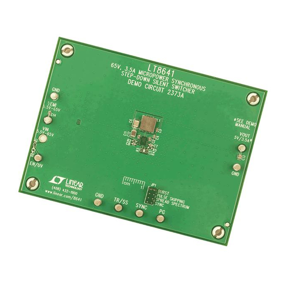
Demonstration circuit 2373A is a 65V, 3.5A micropower
synchronous step-down Silent Switcher
spectrum frequency modulation featuring the
The demo board is designed for 5V output from a 5.5V to
65V input. The wide input range allows a variety of input
sources, such as automotive batteries and industrial sup-
plies. The LT8641 is a compact, ultralow emission, high
efficiency, high speed synchronous monolithic step-down
switching regulator that consumes only 2.5μA of quiescent
current when output is regulated at 5V. Top and bottom
power switches, compensation components and other
necessary circuits are inside of the LT8641 to minimize
external components and simplify design.
The SYNC pin on the demo board is grounded by default
for low ripple burst mode operation. Move JP1 to PULSE
SKIPPING position can change the operation mode to
pulse-skipping operation. Once JP1 is on SPREAD SPEC-
TRUM position, V
is applied to the SYNC pin for low
CC
EMI spread spectrum operation. To synchronous to an
external clock, move JP1 to SYNC and apply the external
clock to the SYNC turret. Figure 1 shows the efficiency of
the circuit at 12V and 24V input in Burst Mode
(input from V
turret pin). Figure 2 shows the LT8641
IN
performance summary
SYMBOL
PARAMETER
V
Input Voltage Range
IN
V
Output Voltage
OUT
I
Maximum Output Current
OUT
f
Switching Frequency
SW
EFF
Efficiency
DEMO MANUAL DC2373A
65V, 3.5A Micropower Synchronous
Step-Down Silent Switcher
temperature rising on DC2373A demo board under differ-
with spread
ent load conditions. The rated maximum load current is
®
LT
8641.
3.5A, while derating is necessary for certain input voltage
®
and thermal conditions.
The demo board has an EMI filter installed. Under burst
and spread spectrum operation, the EMI performances of
the board (with EMI filter) are shown in Figure 3 and 4. The
red lines in Figure 3 and 4 are CISPR25 Class5 peak limit.
To achieve EMI/EMC performance as shown in Figure 3
and 4, the input EMI filter is required and the input voltage
should be applied at VEMI turret pin.
This board is suitable for a wide range of automotive,
telecom, industrial, and other applications.
The LT8641 data sheet gives a complete description of
the part, operation and application information. The data
sheet must be read in conjunction with this demo manual
for DC2373A.
Design files for this circuit board are available at
http://www.linear.com/demo/DC2373A
L, LT, LTC, LTM, Linear Technology, Silent Switcher, Burst Mode and the Linear logo are
operation
®
registered trademarks of Linear Technology Corporation. All other trademarks are the property
of their respective owners.
Specifications are at T
CONDITIONS
Derating Is Necessary for Certain V
Thermal Conditions
V
= 12V, I
= 1A
IN
OUT
= 25°C
A
MIN
5.5
4.8
and
3.5
IN
1.85
LT8641
TYP
MAX
UNITS
65
V
5
5.2
V
A
2
2.15
MHz
94
%
dc2373af
1
Advertisement

Related Manuals for Linear Technology 2373A


Summary of Contents for Linear Technology 2373A
- Page 1 JP1 to SYNC and apply the external http://www.linear.com/demo/DC2373A clock to the SYNC turret. Figure 1 shows the efficiency of L, LT, LTC, LTM, Linear Technology, Silent Switcher, Burst Mode and the Linear logo are the circuit at 12V and 24V input in Burst Mode operation ®...
-
Page 2: Quick Start Procedure
DEMO MANUAL DC2373A Quick start proceDure DC2373A is easy to set up to evaluate the performance b. A voltmeter can be placed across the output terminals of the LT8641. Refer to Figure 5 for proper measurement in order to get an accurate output voltage measure- equipment setup and follow the procedure below: ment. - Page 3 DEMO MANUAL DC2373A Quick start proceDure 12V INPUT 24V INPUT DC2373a F01 Figure 1. Efficiency vs Load Current at 2MHz Switching Frequency = 12V, f = 1MHz = 24V, f = 1MHz = 12V, f = 2MHz = 24V, f = 2MHz LOAD CURRENT (A) DC2373a F02...
- Page 4 DEMO MANUAL DC2373A Quick start proceDure FREQUENCY (MHz) DC2373a F03 Figure 3. LT8641 Demo Circuit EMI Performance in CISPR25 Radiated Emission Test, Antenna Polarization: Vertical (V = 14V, V = 5V, I = 3.5A, 2MHz Switching Frequency) FREQUENCY (MHz) DC2373a F04 Figure 4.
- Page 5 DEMO MANUAL DC2373A Quick start proceDure Figure 5. Proper Measurement Equipment Setup Figure 6. Measuring Output Ripple dc2373af...
-
Page 6: Parts List
DEMO MANUAL DC2373A parts List ITEM REFERENCE PART DESCRIPTION MANUFACTURER/PART NUMBER Required Circuit Components C2, C12 CAP , X7R, 0.1µF, 100V, 10%, 0603 MURATA, GRM188R72A104KA35D C4, C8 CAP , X7R, 0.1µF, 16V, 10%, 0603 MURATA, GRM188R71C104KA01D CAP , C0G, 10pF, 25V, 5%, 0603 AVX, 06033A100CAT2A CAP , X5R, 100µF, 10V, 20%, 1210 MURATA, GRM32ER61A107ME20L... -
Page 7: Schematic Diagram
Information furnished by Linear Technology Corporation is believed to be accurate and reliable. However, no responsibility is assumed for its use. Linear Technology Corporation makes no representa- tion that the interconnection of its circuits as described herein will not infringe on existing patent rights. - Page 8 Linear Technology Corporation (LTC) provides the enclosed product(s) under the following AS IS conditions: This demonstration board (DEMO BOARD) kit being sold or provided by Linear Technology is intended for use for ENGINEERING DEVELOPMENT OR EVALUATION PURPOSES ONLY and is not provided by LTC for commercial use. As such, the DEMO BOARD herein may not be complete in terms of required design-, marketing-, and/or manufacturing-related protective considerations, including but not limited to product safety measures typically found in finished commercial goods.
- Page 9 Mouser Electronics Authorized Distributor Click to View Pricing, Inventory, Delivery & Lifecycle Information: Analog Devices Inc. DC2373A...
Need help?
Do you have a question about the 2373A and is the answer not in the manual?
Questions and answers