Advertisement
DESCRIPTION
Demonstration circuit DC2367A features the
µModule
regulator, a tiny low-profile high-performance
®
high efficiency dual step-down regulator for DDR power.
LTM4632 has an operating input voltage range of 3.6V
to 15V. The output voltage of channel 1 (VDDQ) is resis-
tor programmable from 0.6V to 2.5V and is capable of
delivering up to 3A of output current. The output voltage
of channel 2 (VTT) is set to regulate ½ of the voltage on
the VDDQIN pin which can provided by either the channel
1 output or an external reference voltage. It can source or
sink up to 3A of output current. A 10mA buffered output
of VDDQIN/2 is also provided for supplying VREF voltage
for DDR memory. DC2367A also provides the option for
paralleling channels 1 and 2 together for up to 6A capable
VTT rail. LTM4632 is a complete DC/DC DDR dual point
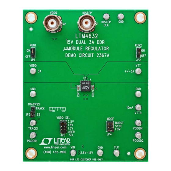
BOARD PHOTO
Arrow.com.
Downloaded from
Ultrathin µModule Regulator for DDR-QDR4
LTM
4632EV
®
DEMO MANUAL DC2367A
Memory VDDQ, VTT and VREF
of load regulator in a low-profile thermally enhanced
6.25mm × 6.25mm × 1.82mm LGA package requiring
only a few input and output capacitors. Output voltage
tracking is available through the TRACK/SS pin for supply
rail sequencing. External clock synchronization is avail-
able through the SYNC/MODE pin. For high efficiency at
low load currents the MODE pin jumper (JP4) selects the
Burst Mode
option for operation in less noise sensitive
®
applications. The LTM4632 data sheet must be read in
conjunction with this demo manual for working on or
modifying demo circuit 2367A.
Design files for this circuit board are available at
http://www.linear.com/demo/DC2367A
L, LT, LTC, LTM, Linear Technology, the Linear logo, µModule and Burst Mode are registered
trademarks of Linear Technology Corporation. All other trademarks are the property of their
respective owners.
LTM4632EV
dc2367af
1
Advertisement
Table of Contents

Related Manuals for Linear Technology DC2367A


Summary of Contents for Linear Technology DC2367A
- Page 1 1 and 2 together for up to 6A capable L, LT, LTC, LTM, Linear Technology, the Linear logo, µModule and Burst Mode are registered VTT rail. LTM4632 is a complete DC/DC DDR dual point trademarks of Linear Technology Corporation. All other trademarks are the property of their respective owners.
- Page 2 OUT2 (See Figure 3) QUICK START PROCEDURE Demonstration circuit DC2367A is an easy way to evaluate 3. With power off, connect the loads, input voltage supply the performance of the LTM4632. Please refer to Figure 1 and meters as shown in Figure 1.
- Page 3 DEMO MANUAL DC2367A QUICK START PROCEDURE – VARIALE RESISTOR (OPTIONAL) FOR SINK CURRENT TEST LOAD LOAD 0A TO 3A 0A TO 3A – – – – – – – + – – Figure 1. Test Setup RUN2 = OFF RUN1 = OFF...
- Page 4 DEMO MANUAL DC2367A QUICK START PROCEDURE = 50mV/DIV OUT1 = 2A/DIV OUT1_STEP dc2367a F04 = 12V = 2.5V OUT1 = 100µF ×2, 10µF ×1 OUT1 Figure 4. VDDQ Load Transient Response (0A to 1.5A Load Step) = 50mV/DIV OUT2 = 2A/DIV...
- Page 5 DEMO MANUAL DC2367A QUICK START PROCEDURE dc2367a F06 = 12V = 2.5V OUT1 = 3A OUT1 = 1.25V OUT2 = 3A OUT2 = 1MHz = 25°C, NO FORCED AIRFLOW Figure 6. 12V Full Load Thermal Capture dc2367af Arrow.com. Arrow.com. Arrow.com.
- Page 6 DEMO MANUAL DC2367A PARTS LIST ITEM REFERENCE PART DESCRIPTION MANUFACTURER/PART NUMBER Required Circuit Components CIN1, CIN2 CAP ., 4.7µF, X5R, 16V, 10%, 0603 TDK - C1608X5R1C475K080AC COUT7, COUT9 CAP ., 10µF, X5R, 6.3V, 10%, 0805 MURATA, GRM219R60J106KE19D COUT1, COUT2, COUT3, COUT4, COUT6 CAP ., 100µF, X5R, 6.3V, 20%, 1206...
- Page 7 Information furnished by Linear Technology Corporation is believed to be accurate and reliable. However, no responsibility is assumed for its use. Linear Technology Corporation makes no representa- tion that the interconnection of its circuits as described herein will not infringe on existing patent rights.
- Page 8 Linear Technology Corporation (LTC) provides the enclosed product(s) under the following AS IS conditions: This demonstration board (DEMO BOARD) kit being sold or provided by Linear Technology is intended for use for ENGINEERING DEVELOPMENT OR EVALUATION PURPOSES ONLY and is not provided by LTC for commercial use. As such, the DEMO BOARD herein may not be complete in terms of required design-, marketing-, and/or manufacturing-related protective considerations, including but not limited to product safety measures typically found in finished commercial goods.
Need help?
Do you have a question about the DC2367A and is the answer not in the manual?
Questions and answers