Advertisement
Description
Demonstration circuit 2125 is a small, highly-integrated,
non-isolated PoE Powered Device (PD) solution. It features
a PD Interface Controller
(LT
a PoE Power Sourcing Equipment (PSE), an ideal diode
bridge controller (LT4321), which minimizes bridge losses,
and a DC/DC µModule
regulator
®
The DC2125 is initially configured as a 38.7W LTPoE ++
PD that is capable of providing 12V and 3A at the output.
Users can configure the PD circuit to be an IEEE802.3
performance summary
SYMBOL
CONDITIONS
V
RJ-45 Port Voltage Range
PORT
I
Maximum Current from V
OUT(MAX)
V
Output Voltage
OUT
ΔV
Output Voltage Ripple at V
OUT(RIPPLE)
ΔV
Output Voltage Regulation, I
OUT(REG)
Efficiency
Maximum Efficiency, V
f
Switching Frequency
SW
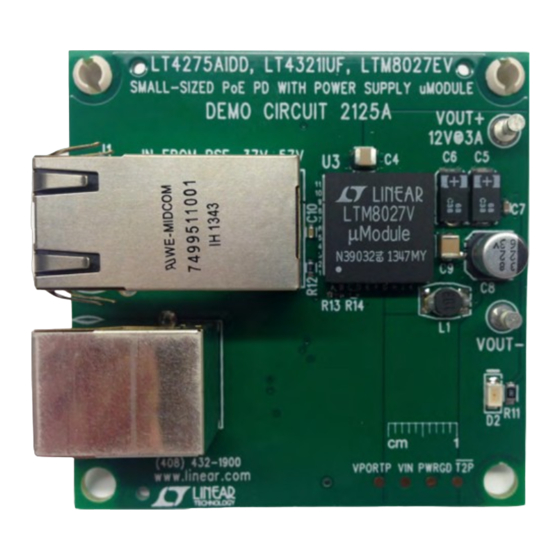
BoarD photos
Top Side
Small Highly-Integrated Highly-Efficient
Non-Isolated PoE Powered Device
4275), which interfaces with
®
(LTM
8027).
®
Specifications are at T
+ to V
–
OUT
OUT
= 50V, I
= 3A
PORT
OUT
= 0A to 3A, V
OUT
PORT
= 41V, I
= 3A
PORT
OUT
DEMO MANUAL DC2125
LT4275, LT4321, LTM8027
compliant Type 2 (25.5W, "at") or Type 1 (13W, "af") PD
by changing the RCLASS and RCLASS ++ resistors. See
the LT4275 data sheet for further information. The output
voltage of the LTM8027 can be easily configured for differ-
ent output voltages as shown in the LTM8027 data sheet.
Gerber files for this circuit board are available. Call
the LTC factory.
™
L, LT, LTC, LTM, Linear Technology and the Linear logo are registered trademarks of Linear
Technology Corporation. All other trademarks are the property of their respective owners.
= 25°C
A
UNITS
37V to 57V
12V (typ)
58mVpp (typ)
±0.031% (typ)
90% (typ)
300kHz (typ)
Bottom Side
3A
dc2125f
1
Advertisement
Table of Contents

Related Manuals for Linear Technology DC2125


Summary of Contents for Linear Technology DC2125
- Page 1 ™ PD that is capable of providing 12V and 3A at the output. L, LT, LTC, LTM, Linear Technology and the Linear logo are registered trademarks of Linear Users can configure the PD circuit to be an IEEE802.3 Technology Corporation. All other trademarks are the property of their respective owners.
-
Page 2: Typical Performance Characteristics
DEMO MANUAL DC2125 typical performance characteristics Top Side Bottom Side Figure 1. Thermal Pictures – V = 50V, I = 3A PORT Efficiency and Regulation dc2125f... -
Page 3: Quick Start Procedure
DC2125 over its full operating load range. Power-up the LTPoE ++ PSE. NOTE: The DC1814A-A LTPoE ++ LOAD CAT-5E CAT-6 – CABLE EXAMPLE: DC1814A-AE DC2125 F01 Figure 2. Setup Diagram for the DC2125 Using an LTPoE ++ PSE and a Load dc2125f... -
Page 4: Parts List
DEMO MANUAL DC2125 parts list REFERENCE PART DESCRIPTION MANUFACTURER/PART NUMBER Required Circuit Components C1, C3 CAP., X7S, 0.047µF 100V, 10%, 0603 TDK, C1608X7S2A473K CAP., X7R, 47nF 100V, 10%, 0805 AVX, 08051C473KAT2A CAP., X7R, 22µF 16V, 20%, 1210 AVX, 1210YC226MAT2A C5, C6 CAP., TQC, 68µF 16V, 7343... - Page 5 DEMO MANUAL DC2125 schematic Diagram dc2125f...
- Page 6 DEMO MANUAL DC2125 schematic Diagram dc2125f...
-
Page 7: Schematic Diagram
Information furnished by Linear Technology Corporation is believed to be accurate and reliable. However, no responsibility is assumed for its use. Linear Technology Corporation makes no representa- tion that the interconnection of its circuits as described herein will not infringe on existing patent rights. - Page 8 Linear Technology Corporation (LTC) provides the enclosed product(s) under the following AS IS conditions: This demonstration board (DEMO BOARD) kit being sold or provided by Linear Technology is intended for use for ENGINEERING DEVELOPMENT OR EVALUATION PURPOSES ONLY and is not provided by LTC for commercial use. As such, the DEMO BOARD herein may not be complete in terms of required design-, marketing-, and/or manufacturing-related protective considerations, including but not limited to product safety measures typically found in finished commercial goods.
- Page 9 X-ON Electronics Largest Supplier of Electrical and Electronic Components Click to view similar products for category: Power Management IC Development Tools Click to view products by manufacturer: Analog Devices Other Similar products are found below : EVAL-ADM1168LQEBZ EVB-EP5348UI MIC23451-AAAYFL EV MIC5281YMME EV DA9063-EVAL ADP122-3.3-EVALZ ADP130- 0.8-EVALZ ADP130-1.2-EVALZ ADP130-1.5-EVALZ ADP130-1.8-EVALZ ADP1714-3.3-EVALZ ADP1716-2.5-EVALZ ADP1740-1.5- EVALZ ADP1752-1.5-EVALZ ADP1828LC-EVALZ ADP1870-0.3-EVALZ ADP1871-0.6-EVALZ ADP1873-0.6-EVALZ ADP1874-0.3- EVALZ ADP1882-1.0-EVALZ ADP199CB-EVALZ ADP2102-1.25-EVALZ ADP2102-1.875EVALZ ADP2102-1.8-EVALZ ADP2102-2-...
Need help?
Do you have a question about the DC2125 and is the answer not in the manual?
Questions and answers