Advertisement
INTRODUCTION
- Device safety is only guaranteed when the safety and usage instructions are respected, so keep them handy. Make sure these instructions are received by the installer and end user.
- This product must only be used for the purpose for which it was designed. Any other form of use should be considered improper and/or dangerous. If you have any doubts, contact the GEWISS SAT technical support service.
- The product must not be modified. Any modification will annul the warranty and may make the product dangerous.
- The manufacturer cannot be held liable for any damage if the product is improperly or incorrectly used or tampered with.
- Contact point indicated for the purposes of fulfilling the applicable EU directives and regulations:
![]()
GEWISS S.p.a. Via A. Volta, 1 - 24069 Cenate Sotto (BG) - Italy
Tel.: +39 035 946 111 - qualitymarks@gewiss.com

 ATTENTION: the device must only be installed by qualified personnel, observing current regulations and the guidelines for KNX installations.
 ATTENTION: the unused BUS signal cables, and the electrical continuity conductor, must never touch any live elements or the earthing conductor!
ATTENTION: disconnect the mains voltage before installing the device or carrying out any work on it.

If the crossed-out bin symbol appears on the equipment or packaging, this means the product must not be included with other general waste at the end of its working life. The user must take the worn product to a sorted waste centre, or return it to the retailer when purchasing a new one. Products ready for disposal and measuring less than 25cm can be consigned free of charge to dealers whose sales area covers at least 400m², without any purchase obligation. An efficient sorted waste collection for the environmentally friendly disposal of the used device, or its subsequent recycling, helps avoid the potential negative effects on the environment and people's health, and encourages the re-use and/or recycling of the construction materials. GEWISS actively takes part in operations that sustain the correct salvaging and re-use or recycling of electric and electronic equipment
PACK CONTENTS
1 KNX fan coil actuator - DIN rail mounting
1 BUS terminal
1 installation manual
INTENDED USE
The GWA9140 fan coil actuator enables the command of fan coils used for climate control in the rooms.
GENERAL INFORMATION

GWA9140 can be used on 2 conduit and 4 conduit systems, It can command a fan coil with 2- or 3-point heating or cooling valves, and up to 3 fan levels. GWA9140 has 2 inputs for window contacts or for measuring the temperature and monitoring the condensate. An additional relay can command an electric heating or cooling battery, and also be used as a switchover output.
Start-up is simple, thanks to 2 button keys (button keys 11, Figure A) for the fan and heating/cooling mode (to be enabled via ETS).
The operation status is indicated by means of 9 LEDs.
Regulation is via an external control variable or the integrated ambient thermostat. If the thermostat is used, the GWA9145 - NTC 100K TEMPERATURE SENSOR must be connected to the device.
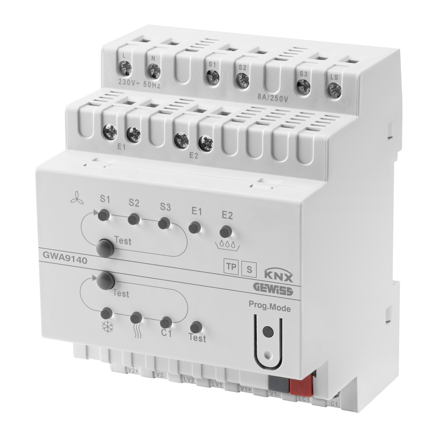
The device is fitted with (figure A):
- Phase and neutral supply terminals: L and N
- Heating valve connection terminals: V1+, V1-, LV1
- Cooling valve connection terminals: V2+, V2-, LV2
- Fan connection terminals: S1,S2, S3 and LS
- Terminals for window contact or external temperature sensor (GWA9145): E1
- Terminals for window contact or condensate monitoring: E2
- Terminals for the additional relay: C1, LC1
- Status LED for fan speed S1,S2,S3, inputs, operating mode, additional relay and test mode
- Status LED for contact E1 (LED ON = contact closed, LED flashing = probe faulty)
- Status LED for contact E2 (LED ON = contact closed, condensate info)
![]() LED ON = cooling valve open. The LED flashes if the cooling valve should be open but the heating valve is still open
LED ON = cooling valve open. The LED flashes if the cooling valve should be open but the heating valve is still open![]() LED ON = the heating valve is open. The LED flashes if the heating valve should be open but the cooling valve is still open.
LED ON = the heating valve is open. The LED flashes if the heating valve should be open but the cooling valve is still open.- LED C1 - status LED for the additional relay
- Test LED - ON if test mode is active (it must be activated via configuration)
- Test push-buttons for regulating the level of ventilation, valves and additional relay C1
- LED for programming
- Programming push-button
- BUS terminals


FUNCTIONS
- Device for commanding fan coils
- Can be used in 2-conduit and 4-conduit systems
- Suitable for 2- and 3-point valves
- For max. 3 ventilation levels
- Simple start-up thanks to 2 button keys for fan test and heating/cooling mode (to be enabled via ETS)
- The additional relay C1 for heating/cooling can also be used as a switchover output
- 2 inputs for window contact or external temperature sensor (GWA9145) and condensate monitoring
- Command via external control variable or with integrated ambient thermostat
- Mode changeover via the presence object and the window object
- The reference temperature can be adapted in cooling mode according to the outside temperature
- In the case of an external regulator, a configurable emergency program can be defined. In the case of an internal regulator, the operating mode following a restart can be defined
- Monitoring of the fan coil filter via configurable signalling with an indication of the operating time
ASSEMBLY AND CONNECTION
For assembly, refer to figure C.

For the electrical connections, refer to figure B.


To connect the KNX BUS terminal, refer to figure D.

ATTENTION
- Deactivate the voltage supply before making any connections
- Assemble on the DIN rail, as per EN 60715 (figure C)
- Pay attention to the polarity of the BUS terminal (figure D)
Connection (figure B)
- Respect the connection diagram
- 2-point valves for heating and cooling and additional relay C1
- 2-point valve for heating only/cooling only and additional relay C1
- 3-point valves for heating and cooling and additional relay C1
- 3-point valve for heating only/cooling only and additional relay C1
- Coupling for inputs 1 and 2
MAINTENANCE
The device does not require any maintenance. Use a dry cloth if cleaning is required.
PROGRAMMING
The device must be configured with the ETS software.
Detailed information about the configuration parameters and their values is given in the Technical Manual (www.gewiss.com).
TECHNICAL DATA
| Operating voltage | 230V |
| Frequency | 50 Hz |
| Power in standby | 1.9W |
| KNX BUS voltage | 21–32V DC |
| Current absorbed by KNX BUS | 7.5 mA |
| Minimum charge for additional relay, fan relay | 12V / 100 mA |
| Type of contact for fan relay/additional relay | μ contact |
| Type of valve output contact | ε contact (triac) |
| Input E1/E2 | connect the zero potential contact check SELV! |
| Max. length of cable E1/E2 | 5m |
| Operation | Type 1 |
| Software | class A |
| Additional relay output | 16A / 250V cos φ = 1 |
| Fan relay output | 8A / 250V AC |
| Operating temperature | from –5°C to +45°C |
| Protection class | II with correct assembly |
| Type of protection | IP 20 |
| Pollution rating | 2 |
| Nominal transitory overvoltage | 4 kV |
| Size | 4 DIN modules |
| Reference Standards | Low Voltage Directive 2014/35/EU Electromagnetic Compatibility Directive 2014/30/EU EN 60730-1 EN 60730-2-9 |
| Certifications | KNX |
TEST MODE (for start-up only)
The sole purpose of test mode is to check the system, for instance during start-up or when searching for errors. The inputs E1 and E2 can also be checked. This function must be activated via the appropriate configuration using ETS.
Indications for test mode:
- All the settings are possible without any limitation, using the button keys.
- Regulation and BUS telegrams are deactivated.
- In test mode, all the ventilation levels and the two valves are always powered with standard current, regardless of the parameters.
- The valves and fan are commanded until they are manually deactivated.
- The condensate alarm is not taken into consideration.
- Avoid operation statuses that are not permitted (e.g. heating and cooling valves open simultaneously).
Activating test mode:
- Test mode is activated at the restart of the device or after downloading the application program via ETS. The test LED flashes for 1 min. (test mode is active). The GWA9140 will then switch to normal operation.
- Press test button key A or test button key B. The GWA9140 will switch to test mode and the LED light will be fixed.
Commanding the fan:
- Press test button key A several times to activate the levels, one after the other.
Commanding the valves / Switchover to additional relay:
- Press test button key B several times until the required valve or the additional relay C1 is selected.
Visualisation of the heating/cooling valve status in test mode.
| LED status | 3-point valves / 2-point valves |
 OFF OFF | The valve is not commanded |
| ON | The valve is opened (V2+) |
| Flashing | The valve is closed (V2-) / The valve is closed (no longer commanded) |
 OFF OFF | The valve is not commanded |
| ON | The valve is opened (V1+) |
| Flashing | The valve is closed (V1-) / The valve is closed (no longer commanded) |
Terminating test mode:
- Test mode is terminated when the device restarts.
Restart:
- Press the 2 test button keys simultaneously (> 2 s)
- Download the application program via ETS
- Stop and reset the BUS voltage Punto di contatto indicato in adempimento ai fini delle direttive e regolamenti UE applicabili:
Contact details according to the relevant European Directives and Regulations:
GEWISS S.p. A. Via A.Volta, 1 IT-24069 Cenate Sotto (BG) Italy tel: +39 035 946 111 E-mail: qualitymarks@gewiss.com
 |  | +39 035 946 111 8.30 - 12.30 / 14.00 - 18.00 monday ÷ friday |  | +39 035 946 260 |  | sat@ gewiss.com www.gewiss.com |


Documents / Resources
References
Download manual
Here you can download full pdf version of manual, it may contain additional safety instructions, warranty information, FCC rules, etc.
Download Gewiss CHORUS GWA9140 - KNX Fan Coil Actuator - DIN Rail Mounting Manual
Advertisement


Need help?
Do you have a question about the CHORUS GWA9140 and is the answer not in the manual?
Questions and answers