
Subscribe to Our Youtube Channel
Related Manuals for Gewiss Chorus GWA1521


Summary of Contents for Gewiss Chorus GWA1521
- Page 1 MANUAL ZIGBEE CONFIGURATION BINDING BETWEEN THE GWA1521 ACTUATOR AND THE GWA1514 H O SENSOR TECHNICAL MANUAL...
- Page 2 page 2 | Z | TECHNICAL MANUAL: BINDING BETWEEN GWA1521 AND GWA1415...
-
Page 3: Table Of Contents
CONTENTS CONTENTS ................................3 AIM OF THIS PUBLICATION ..........................4 ZIGBEE KEY – USEFUL TERMS .......................... 4 TECHNICAL FILES ..............................5 DIMENSIONS ................................6 BREAKDOWN OF THE ZIGBEE DEVICES ......................7 ELECTRIC DIAGRAMS ............................8 CONFIGURATION ..............................9 : ..................... 9 REATING AND JOINING TO THE EE NETWORK : .......................... -
Page 4: Aim Of This Publication
AIM OF THIS PUBLICATION This manual is designed for the installer responsible for configuring the ZigBee system. It explains how to make the binding between the GWA1521 and GWA1415 devices. ZIGBEE KEY – USEFUL TERMS Binding: The association between an actuator and a sensor in order to carry out a certain function Coordinator: The ZigBee device that carries out the following tasks:... -
Page 5: Technical Files
TECHNICAL FILES GWA1521 General loads actuator ATEGORY 230V AC / 50Hz UPPLY VOLTAGE 1 NO 10A (AC1) 230V AC UTPUT CONTACTS OF OUTPUT CHANNELS (W): DISPERSIBLE POWER 500W MOTOR POWER 3 dBm UTPUT POWER 150W LAMPS 450W OADS CONTROLLED BY TOROIDAL TRANSFORMERS 600W OADS CONTROLLED BY ELECTRONIC TRANSFORMERS 230V... -
Page 6: Dimensions
DIMENSIONS GWA1521 GWA1514 page 6 | Z | TECHNICAL MANUAL: BINDING BETWEEN GWA1521 AND GWA1415... -
Page 7: Breakdown Of The Zigbee Devices
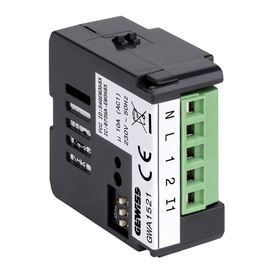
BREAKDOWN OF THE ZIGBEE DEVICES GWA1514 A1: Push-button/multi-purpose red LED A2: Test and alarm silencer push-button/red alarm LED GWA1521 A1. DIP-switch with 3 one-way switches A2. Miniature button key for joining functions A3. Status LED TECHNICAL MANUAL: BINDING BETWEEN GWA1521 AND GWA1415 | Z | page 7... -
Page 8: Electric Diagrams
ELECTRIC DIAGRAMS GWA1521 N. Power supply neutral L. Power supply phase 1. Output common wire 2. NO output I1. Local command input page 8 | Z | TECHNICAL MANUAL: BINDING BETWEEN GWA1521 AND GWA1415... -
Page 9: Configuration
CONFIGURATION If the ZigBee network hasn't yet been created, proceed as follows: 1. Choose which device will have the role of coordinator 2. Activate the procedure to create the ZigBee network via the coordinator 3. After creating the network, activate Permit Join 4. -
Page 10: Sensor (Gwa1514) Factory Reset
SENSOR (GWA1514) FACTORY RESET Press and hold button/status LED A1 until the LED flashes continuously (it will first of all make a single flash, then a double one, then it will continue flashing). ACTUATOR (GWA1521) FACTORY RESET Press and hold the Permit Join activation push-button (A2) for at least 10 seconds. The status LED will flash red and green alternately for 3 seconds, then become red fixed. - Page 11 TECHNICAL MANUAL: BINDING BETWEEN GWA1521 AND GWA1415 | Z | page 11...
Need help?
Do you have a question about the Chorus GWA1521 and is the answer not in the manual?
Questions and answers