Table of Contents

Subscribe to Our Youtube Channel
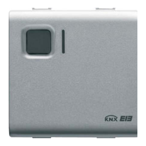
Summary of Contents for Gewiss Chorus GW 10 766
- Page 1 Easy 1 channel switch actuator 16A GW 10 766 GW 12 766 GW 14 766 Technical Manual...
-
Page 2: Table Of Contents
Summary Introduction ..............................3 Application ..............................4 Limits to the associations ........................4 Block diagrams ..........................4 “Settings” menu ............................5 Parameters ............................5 Communication objects ........................6 ... -
Page 3: Introduction
1 Introduction This manual describes the functions of the device named GW1x766 “Easy 1 channel switch actuator 16A” and how to use the ETS configuration software to change the settings and configurations. -
Page 4: Application
2 Application The Easy 1 channel switch actuator 16A is used to activate/deactivate an electric load using a 16 A relay. The device has 1 channel with an output that has a changeover contact to which two terminals are connected, one with a normally open (NO) contact function and the other with a normally closed (NC) functions to which it is possible to connect the load according to requirements. -
Page 5: "Settings" Menu
3 “Settings” menu Here it is possible to configure the programming mode between ETS mode (S-Mode) and Easy mode by the Easy controller software (Kit GW90837, Kit GW90838, GW90840) and enable the night localisation of the actuator (see Diag 3.1). Diag. -
Page 6: Communication Objects
3.1.2 Night lighting This is to activate/deactivate the lighting function of the front yellow amber coloured LEDs; the settings are: • deactivated The front yellow amber coloured LED will never be working, therefore when the load is deactivated (open if NO/closed if NC) the front indicator light will not be backlit. •... -
Page 7: "Timed Execution" Menu
4 “Timed execution” menu The Timed execution menu lists all the parameters needed to enable and configure the timed activation of the relay (staircase light function) as shown in Diag. 4.1. Diag. 4.1 4.1 Parameters 4.1.1 Activate function Here you can enable and configure the function and make visibles the Activation time parameter, the Warning time parameter and the relative Timed switch communication object. -
Page 8: Communication Objects
4.1.2 Activation time Here you can set the activation time value. It is possible to set a value between 1 second and 24 hours. When the device receives the START timed activation command, it switches the relay (close NO contact / open NC contact) and at the end of the activation time setting, it automatically switches the contact back to normal conditions (open NO contact / close NC contact);... -
Page 9: "Priority Commands Execution" Menu
5 “Priority commands execution” menu Here is possible to enable the forced positioning mode functions used by the device (see Diag. 5.1). Diag. 5.1 5.1 Parameters 5.1.1 Activate function This is to enable the function and make the Priority command communication object visible. The forced positioning function, according to the command received from the bus, forces the device into a specific condition mode until a forced positioning deactivation command is received;... -
Page 10: Communication Objects
When the forced positioning is deactivated the device sets the changeover contact according to the last command received from the bus when the forced positioning was activated; if it receives a switch ON/OFF command or an execute/learn scene command, the last of these commands received during the time the forced positioning was activated will be performed as soon as the forced positioning is deactivated. -
Page 11: "Scene Management" Menu
6 “Scene Management” menu Here is possible to enable the scene functions used by the device (see Diag. 6.1). Diag. 6.1 6.1 Parameters 6.1.1 Activate function This is to enable the function and make the Scene communication object visible. The scenes function sends two possible commands to the device: −... -
Page 12: Communication Objects
6.2 Communication objects The Scene menu makes the following communication object visible (see Diag. 6.2.): Diag. 6.2 6.2.1 Scene Using this communication object, the device is able to receive the perform and memorise scene commands from the bus. The enabled flags are C (communication), W (written by bus) . The standard format of the object is 18.001 DPT_SceneControl, the size of the object is 1 byte and it is used to receive the execute/learn scene bus commands. - Page 13 NOTES...


Need help?
Do you have a question about the Chorus GW 10 766 and is the answer not in the manual?
Questions and answers