
Related Manuals for AngelTrax SDX2


Summary of Contents for AngelTrax SDX2
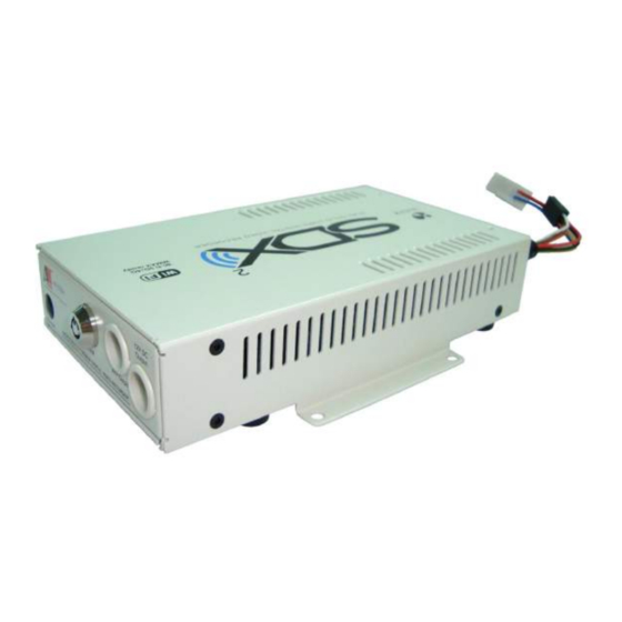
- Page 1 Stand-Alone 4Ch Real Time Record Mobile DVR User Manual (SDX-V1) Please read this user manual completely before operating this DVR system and keep it in a safe place for future reference.
-
Page 2: Table Of Contents
TABLE OF CONTENTS Table of Contents ………………………………………………………….…….…… Introduction …………………………………………………………………….….…….. 2 Important Safety Information …………………………………………………..……… 2 Unpacking Your System …………………………………………………….….……… 3 Control Panel and Function ………………………………………….…….…….……. 5 Installation ………………………………………………………………………..……… 8 Before Operation …………………………………………………………………..…… 11 Operation ……………………………………………………………………………..…. 11 OSD (On Screen Display) Menu Setting Operation Process ……………..…….. 12 Screen Instruction ……………………………………………………….……...……... -
Page 3: Introduction
INTRODUCTION Thank you for purchasing our unique Mobile DVR system. To ensure that you optimize the full capabilities of this product, please read this user’s manual before proceeding. Be sure to keep this manual for future reference in case any problems or questions should arise. -
Page 4: Unpacking Your System
UNPACKING YOUR SYSTEM Your DVR system will include the followings: 1 x DVR unit 1 x Rear Cover and screws 2 x Keys 4 x Screws 1 x Power and Ignition Cable (POWL026A+B) 3 x Spare Fuse (5A) 1 x A/V Adapter Cable 1 x RCA Cable 1 x DB15 Cable (BNC Connector) 1 x Wireless Remote Control... - Page 5 Optional Accessory GPS-E1 (external GPS unit) AP router box Driver Action and Extension Cable (5M)
-
Page 6: Control Panel And Function
CONTROL PANEL AND FUNCTION Front Panel 1. IR remote control receiver 3. Audio/Video output terminal 2. Font panel key socket 4. 12V DC output power socket 5. Audio/Video output terminal 11. SD card slot 2 6. Reset button 12. SD Card Slot 1 indicator 7. - Page 7 Rear Panel 16. DC power cord connecting socket 23. Driver action device connecting socket 17. External GPS unit connecting socket 24. G-sensor box connecting socket 18. Function Expansion I/O socket 25. Trigger record device connecting socket 19. System monitor connecting socket 26.
- Page 8 IR Remote Control Menu button Move up key Move down key Move left button Move right button Enter button Value up button Value down button Zoom button Sequence mode button Copy button Lock button (Key Lock) Rewind button Play button Pause button Stop button POP button...
-
Page 9: Installation
INSTALLATION Please refer to the installation process as the following drawing: 1. Insert the key to key socket and turn right to open the front cover. 2. SD card installation Insert the SD card into the SD card slot on front panel. There are 2 SD card slots available. - Page 10 Please refer to the installation process as the following drawing: 3. Audio/Video output connection Connect the monitor to A/V output terminal. There are two A/V output terminals for easy install. 4. System camera installation Connect one end of camera cable to Camera and the other end to Video Input port at the back of DVR.
- Page 11 6. G-sensor box connection (optional) Connect the G Sensor box to G Sensor box socket. Make sure the G sensor box connected to DVR and setting the G sensor box type G1(2D G sensor box) or G2 (3D G sensor box). Please refer to the “SUB Menu”...
-
Page 12: Before Operation
BEFORE OPERATION The system will auto detect the hardware and enter Recording mode while hardware is in normal condition. If the system has not set the time yet, please press MENU key to “Date/Time setup” to set the correct time. If the screen has no video, please check whether A/V input connector is connected with camera correctly or not. -
Page 13: Osd (On Screen Display) Menu Setting Operation Process
OSD (On Screen Display) Menu Setting Operation Process 1. Press Menu button to enter the MAIN MENU selection mode. 2. Press Up / Down button to select the item for setting. 3. Press Enter button to enter Sub Menu to select item for setting. 4. -
Page 14: Screen Instruction
Screen Instruction: 85% R BUS-0000000 D:__ __ 12.6V 0MPH H:__ 09/15/11 06:22:04PM 01: Camera 1 02: Camera 2 03: Camera 3 04: Camera 4 BUS0000000: Bus Number or DVR number 85%: The percentage of CF card free space. 1. HDD information [OW]: Recycle recording (Overwrite enabled) [O]: Once recording (Overwrite not allowed) 2. -
Page 15: Osd Setting Operation
OSD Setting Operation 1. Camera Setup Operation 1.1 Title Setup A. Press MENU button to enter menu selection mode. MAIN MENU CAMERA SETUP DATE/TIME SETUP STORAGE SETUP RECORD SETUP NETWORK SETUP PERIPHERAL SUB MENU KEY LOCK SEUP B. Use button to select [CAMERA SETUP] setting section. C. - Page 16 E. Use button to select channel to be set with title. F. Use button to change the camera number. G. Press MENU button to exit for other settings. 1.2 Color Setup A. Press MENU button to enter menu selection mode. B.
- Page 17 D. Use button to select the camera. (CAM 01/02/03/04) E. Use button to select the item to be changed. F. Use button to change the value. G. Press MENU button to exit for other settings. 1.3 Motion Detection A. Press MENU button to enter menu selection mode.
- Page 18 E. Use button to select the area. F. Use button to activate or close the detection of the area. Press button to select all activated or close. [This function will be activated when the record mode is set to “Motion Detection (M)”.] G.
-
Page 19: Date / Time / Daylight Saving Time Setting
2. Date / Time / Daylight Saving Time Setting A. Press MENU button to enter menu selection mode. B. Use button to select [DATE/TIME SETUP] setting section. DATE/TIME SETUP DISPLAY FORMAT: [ MM/DD/YY ] TIME FORMAT: [ 12H ] YEAR [ 2011 ] MONTH [ 09 ]... - Page 20 DAYLIGHT SAVING TIME TURN: [ OFF ] START TIME: (M/D H) 04/10 00:00 MONTH: [ 04 ] WEEK: [2 ND ] DAY: [ SUN ] HOUR: [ 00 ] END TIME: ( M/D H) 11/06 00: 00 MONTH: [ 11 ] WEEK: [1 ST ] DAY:...
-
Page 21: Storage Setup
STORAGE SETUP INFORMATION REC MODE: [ RECYCLE ] FORMAT AUTO FORMAT WITH NEW SD: [ ON ] AUTO FORMAT AFTER FW UPDATE: [ ON ] RECYCLE: OVERWRITE ONCE : STOP RECORDING WHEN FULL 3.1 SD Card Information A.. Use button to select [ INFORMATION ] setting section and press button to enter. - Page 22 B. Use button to select HDD recording mode to RECYLE or ONCE. C. Press Menu button to exit. 3.3 Format A.. Use button to select [HDD FORMAT] setting section and press button to enter. FORMAT SELECT FORMAT [ NO ] SELECT YES AND PRESS ENTER TO START FORMATING B.
-
Page 23: Record Setup
4. Record Setup A. Press Menu button to enter menu selection mode. B. Use button to select [RECORD SETUP] setting section. C. Press button to enter [RECORD SETUP] select mode. RECORD SETUP RECORD MODE CONTINUOUS RECORD ALARM RECORD MOTION RECORD SCHEDULE CONTINUOUS í... - Page 24 CONTINUOUS RECORD RECORD QUALITY: [SUPER ] COMPRESSION/FPSš š š š [ JPEG 60 ] - - RECORD SCHEDULE- - - 0 1 23 4 56 7 89 0 1 2 34 5 6 7 89 01 2 3 CAM REC 1 [ ON ] ííííí...
-
Page 25: Network Setup
d. Motion Record: to set up 4-level record quality, 4 kinds of frame rates and duration for record while detecting alarm or motion. MOTION RECORD RECORD QUALITY: [ SUPER ] COMPRESSION/FPS: [ JPEG 60 ] REC/FULL SCREEN TIME: [ 30 ] SECONDS PRE RECORD: [ 2 MIN ] * Quality: Standard / Normal / High / Super. - Page 26 Wired Network Setup: WIRED NETWORK SETUP MODE [ DHCP] PORT [ 00080 ] [192 168 0XX 0XX ] G/W [ 192 168 0XX 0XX ] MASK [ 255 255 255 000 ] DNS [ 192 168 0XX 00X ] MAC: 00- 14- 62- 00-xx-1E STATUS: DIS-CONNECTED [ SAVE ] Wireless Network Setup:...
- Page 27 Mobile 3G Setup: MOBILE 3G SETUP PORT : [ 0 0080 ] PIN CODE : [ APN NAME : [ [ MODEM STRINGS ] INITIAL DIAL [ OPTIONAL PPP SETTING ] USERNAME: [ PASSWORD: [ [ SAVE ] [ CLEAR ] STATUS : DIS-CONNECTED : 192.168.XXX.XXX...
-
Page 28: Peripheral Setup
D. Press Menu button to exit for other settings. Please refer to the LAN instruction for more details. 7. Peripheral Setup A. Press Menu button to enter menu selection mode. B. Use button to select [PERIPHERAL] setting section. C. Press button to enter [PERIPHERAL] setup select mode. - Page 29 * Key beeping: Buzz when button is pressed (one buzz). * Power on: Buzz when system power on (one buzz). * Video loss: Buzz when video signal is lost. * Alarm Event: Buzz when alarm input is triggered. * Motion: Buzz when system motion is detected. *Time duration: 1~60 seconds to be selected.
- Page 30 * NC = Normal Close: The signal loop is closed under normal condition. When the loop becomes open, alarm will be triggered till the loop becomes closed again. In other words, if the loop keeps opening for a period of time, alarm will keep on being triggered in that time interval.
- Page 31 * After above setting, press (Sequence) button under Live/Record mode to activate this function. 7.4 Password Setup A. Use button to select [PASSWORD SETUP] setting section. B. Press button to enter [PASSWORD SETUP] select mode. PASSWORD SETUP 0 0 0 0 CONFIRM 0 0 0 0 SELECT NUMBER: 0~9...
-
Page 32: Sub Menu Setup
SUB MENU G SENSOR [ G1 ] DVR ID FACTORY DEFAULT UPDATE CODE AUDIO ALERT SETUP NOTIFICATION CH3 VIDEO LOSS EVENT [ OFF ] EVENT LED [ TRIGGER ] LED TIME [ 20 ] POWER DELAY TIME [ 005 ] 8.1 GPS (Optional) This function is available when DVR is connected with the GPS device. - Page 33 G. Press Menu button to exit. 8.2 G-sensor A. Use button to select [G SENSOR [G1] ] setting section. B. Use button to select G SENSOR [G1] or G SENSOR [G2] C. Press button to enter [G SENSOR[G1]] select mode. G SENSOR G VALUE: [ 1.5 ] G...
- Page 34 * Vehicle type: ID/BUS/TAXI/TRAIN/TRUCK to be selected. * Vehicle ID: Can set 8 digits/alphabets (0~9 or A~Z). * Driver/Client: Can set 21 alphabets/digits. C. Use button to select Vehicle type. D. Use to set Vehicle ID/Driver/Client. E. Use to move the cursor. D.
- Page 35 UPDATE CODE LOAD PC PLAYER [ NO ] FIRMWARE UPGRADE [ NO ] EXPORT SETTINGS [ NO ] VERSION: 0.1.42 C. Use button to select YES or NO. D. Press button to RUN this function. E. Press Menu button to exit. 8.6 Audio A.
- Page 36 ALERT SETUP PANIC [ ENABLE ] VIDEO STATUS [ ONCE ] OVER SPEED [ ENABLE ] OVER G-FORCE [ DISABLED ] START RECORDING [ DISABLED ] STOP RECORDING [ DISABLED ] HDD FAIL [ ONCE ] DVR BOOT UP [ ENABLE ] STOP ARM [ ENABLE ] CLOCK SET TO GPS TIME...
- Page 37 8.9 CH3 Video Loss Event A. Use button to select [CH3 VIDEO LOSS EVENT] setting section. CH3 VIDEO LOSS EVENT [OFF] B. Use button to select ON or OFF function. D. Press Menu button to exit. 8.10 Event LED Setting A.
-
Page 38: Key Lock Setup
9. Key Lock Setup A. Press button to enter Menu selection mode. B. Use button to select [KEY LOCK SETUP] setting section. C. Press button to enter [KEYLOCK SETUP] select mode. KEY LOCK SETUP LOCK: [ OFF ] D. Use button to select ON or OFF. -
Page 39: Playback Record Data
PLAYBACK RECORDED DATA There are two ways to playback the recorded data. 1. Playback by Time: a. Press Play button, the screen will display SEARCH menu. b. Use buttons to select the start day and time which you want to playback, then move to “RUN” and press Enter button to playback. - Page 40 d• Press Enter button to playback. e• During playback, press stop button for back to EVENT SEARCH. Press Menu button to exit. * Each page can display 10 events (maximum 1000 events can be recorded). * The event log will be cleared simultaneously when HDD is formatted. * EVENT is recorded on the HDD.
Need help?
Do you have a question about the SDX2 and is the answer not in the manual?
Questions and answers
How do I copy files from the system to a USB or SD card