Table of Contents
Advertisement
Advertisement
Table of Contents

Related Manuals for AngelTrax MiniMicro Plus MDVR


Summary of Contents for AngelTrax MiniMicro Plus MDVR
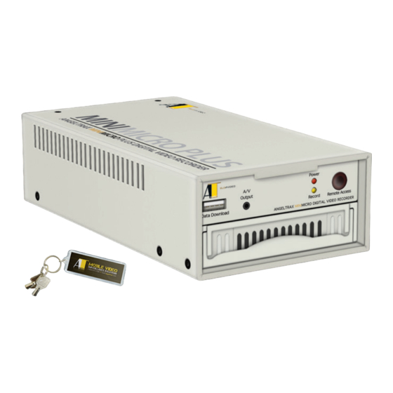
- Page 1 MiniMicro Plus MDVR AngelTrax Mobile Digital Video Recorder Includes Quick Setup Guide Lists all the key features and settings for the MiniMicro Plus MDVR Unit Installation User Menus and Settings Servicing Procedures Mobile DVR Installation, Setup and User Manual...
-
Page 2: Contact Information
| Mobile Video Surveillance Solutions IVS, Inc., dba AngelTrax AngelTrax designs, manufactures and supports mobile video surveillance for the school bus, mass transit, waste management and rail industries. AngelTrax drives the market with patented products, including distinctive DVR systems and Virtual Synchronized Mapping™... -
Page 3: About This Manual
Hybrid Quest™ User Manual Revision This is the June 2013 revision for this User Manual and is copyright, June 2013 of IVS, Inc., dba AngelTrax™ all rights reserved. Exclusion of Liability IVS, Inc.: This software is provided by the copyright and trademark holders and contributors “as is”, and any express or implied warranties, including, but not limited to, the implied warranties of merchantability and fitness for a particular purpose are disclaimed. -
Page 4: Acronym Guide
The stability of the electrical system in the vehicle is critical to the performance and reliability of certain electronics installed onboard. These electronics rely on the vehicle’s power in order to be fully operational. AngelTrax components require stable voltage in order to function properly. -
Page 5: Table Of Contents
MiniMicro Plus Menu Outline ......................... 15 On-Screen Display Diagram ........................17 Using the MiniMicro Plus Menu Section ....................19 Date/Time Setup Section ........................20 Vehicle ID Type and Number Section ....................23 Formatting the HDD Section ......................... 24 AngelTrax | iv... - Page 6 PTZ Section ............................... 41 DVR ID Section ............................41 Factory Default Section ..........................41 Update Code Section ..........................41 Audio Section ............................. 42 Key Lock Setup Section .......................... 43 Section 7: Recommended Preventative Maintenance Firmware Upgrade Section ........................45 AngelTrax | v...
- Page 7 Returning Product for Service Instructions ..................49 Section 9: Common Operations Removing the Hard Drive for Playback Instructions ................. 50 Section 10: Troubleshooting Guide Troubleshooting Guide for the MiniMicro Plus ................... 51 Acronym Guide Acronym Guide ............................52 AngelTrax | vi...
-
Page 8: Section 1: Introduction
Panic ‘PANIC’ button for HDD event mark Delay Shutdown Previous versions have up to a 1 hour delay. Current versions have up to a 4 hour delay. Speed/GPS/Direction Data Optional G-Force Sensor Optional External VSM™ Module Optional AngelTrax | 1... -
Page 9: Parts List (General)
Other items may be included with your system based on your order. Please check the contents of your order carefully. If any items in your order are missing or damaged, please contact AngelTrax immediately by phone at 1.800.673.1788 or by email at support@angeltrax.com for further assistance. -
Page 10: Parts List (Accessory Box)
Wire ties • Stepper drill bit • Portable monitor with audio • Split loom • Fish tape • Various screwdrivers and nut • Connectors for signal inputs drivers (0.3125 in) • Various wire connectors • Rubber grommets AngelTrax | 3... -
Page 11: Section 2: Minimicro Plus Dvr Quick Setup Guide
Please refer to the following sections for information on the NOTICE: Use the arrow buttons located around the ENTER MiniMicro Plus MDVR parts and functions: button near the top of the remote to navigate up, down, left or right on each menu list. Use the plus or minus buttons located Page 2 - Parts List (General) under the arrow buttons to adjust values. -
Page 12: Hdd Format
Menu again if you wish to return to the live camera view. NOTICE: When the vehicle type is changed, the signal wire labels will change. Please refer to the Driver Action-detecting per Vehicle Table, page 13, for more information. AngelTrax | 5... -
Page 13: Minimicro Plus Parts And Functions Diagram
Power • Mounts to bulkhead Output • Hard drive (250GB standard/1TB optional) Record Remote Access Data Download ANGELTRAX MINIMICRO MOBILE DIGITAL VIDEO RECORDER • Power indicator light (red) • Record indicator light (amber) • A/V output • Remote receiver FRONT COVER •... -
Page 14: Installation Best Practices Section
USB port. Allow • Contact the AngelTrax technical support staff sufficient clearance behind the DVR for camera cables, mounting at 1.800.673.1788 before attaching the DVR to cables, Ethernet cables and power cables. -
Page 15: Post-Installation Checklist
Check all switches on vehicle control panel (fans, lights, etc) Make sure dip (delay time) switches are in the correct position Check for missing screws. Make sure panels are installed properly with no cracks in plastic Make sure camera grommets/wire loom are in place AngelTrax | 8... -
Page 16: Minimicro Plus Hardware Installation
Connect the power cable to the power source, then connect the power cable and ignition to the MDVR (see Figure 4). Power-up the MDVR by turning on the vehicle’s ignition. MINIMICRO PLUS ANGELTRAX MINIMICRO PLUS DIGITAL VIDEO RECORDER AngelTrax | 9... - Page 17 Data Download flickers in REC mode mode, make sure the hard drive is in the ‘lock’ position. ANGELTRAX MINIMICRO MOBILE DIGITAL VIDEO RECORDER CAUTION - POWER CONNECTION: { Panic Button } Ensure the connection to the power source is secure, and then connect the cables to the rear of the DVR.
-
Page 18: Panic Button Connection Section
Event Marker Button Event Marker Button Event Marker Button GPS Signal Indicator Power Indicator Power Indicator (red) (red) GPS Signal Indicator Power Indicator GPS Signal Indicator Recording Indicator (green) (green) (*all indicators red) Recording Indicator Recording Indicator (amber) (amber) AngelTrax | 11... -
Page 19: Section 4: Minimicro Plus Connections, Ports And Controls
(1) output of vehicles POWER CONNECTION • Connects the key on the connection wire (yellow), to vehicle ignition ON position • Plugs the power cord to the battery (red) • Connects to the common vehicle ground (black) AngelTrax | 12... -
Page 20: Driver Action-Detecting Per Vehicle Table
DR - Door Open PE2 - Panic Event 2 MR - Microphone D:2 - Door 2 D:2 - Door 2 D:2 - Not used PE3 - Panic Event 3 Reception PANIC PANIC PANIC PANIC PE1 - Panic Event 1 AngelTrax | 13... -
Page 21: Dvr Remote Control Diagram
CAM2 CAM3 AUDIO CAM4 QUAD larger view CAM5 CAM6 CAM7 CAM8 CAM5 CAM6 CAM7 CAM8 CAM5 CAM6 CAM7 CAM8 CAM5 CAM6 CAM7 CAM1 CAM8 CAM2 CAM3 CAM4 Select the Video Channel to View CAM5 CAM6 CAM7 CAM8 AngelTrax | 14... -
Page 22: Section 5: Minimicro Plus Menu And Setup
Pre Record (on/off) (1*) These features are not applicable to the MiniMicro Plus DVR. (2*) These features should be adjusted by AngelTrax personnel only. Please DO NOT adjust. (3*) This feature is not used in the transportation industry. (4*) The PTZ feature is for future applications. Please DO NOT adjust. - Page 23 Alarm Out Factory Default Status (on/off) Time Load (yes/no) Sequence Setup Update Code (5)* Full Screen Format USB (yes/no) Firmware Upgrade USB (yes/no) Password Setup Load PC Player (yes/no) Firmware Upgrade CF (yes/no) Audio Input Volume Output Volume AngelTrax | 16...
-
Page 24: On-Screen Display Diagram
If both doors are open, D:12 will display. If there are no signal wires connected with the doors, D:-- will continue to display. The door signal is marked on the hard drive, and will display in playback. AngelTrax | 17... - Page 25 If a GPS-E1 antenna is installed, the vehicle’s latitude and longitude is displayed on the (Available only with local monitor. When your recorded video data is reviewed with AngelTrax playback software, use of GPS-E1 each channel is marked with your vehicle’s tracking information.
-
Page 26: Using The Minimicro Plus Menu Section
Power up the DVR by turning on the vehicle’s ignition. Record Remote Access Data Download ANGELTRAX MINIMICRO MOBILE DIGITAL VIDEO RECORDER Remove the plastic insert in the battery compartment of the A/V Opening on Door supplied DVR remote. Connect your portable monitor to the composite A/V output on the front of the DVR using the supplied cables (see Figure 1). -
Page 27: Date/Time Setup Section
NOTICE - TIME FORMAT SETTING: ENTER COPY Always program the hour as 24-hour (13:00) so the MDVR can distinguish between AM and PM, and display it accordingly. REWIND PLAY PAUSE STOP AUDIO QUAD CAM1 CAM2 CAM3 CAM4 AngelTrax | 20... - Page 28 As you scroll through the selections, different time zone regions will appear for reference. Select the Menu button to save the settings, and return to the Date/Time Setup menu. Press Menu again to return to the Main Menu. AngelTrax | 21...
- Page 29 If your unit has a GPS antenna, use plus/ minus buttons on the remote to turn ON, and the unit will automatically adjust. If no antenna is present, use plus/minus buttons on the remote to select your preferred Time Zone. AngelTrax | 22...
-
Page 30: Vehicle Id Type And Number Section
Press Menu again if you wish to return to the live camera view. NOTICE - CHANGING VEHICLE ID TYPE: When the vehicle type is changed, the signal wire labels will change. Please refer to the Driver Action- detecting per Vehicle Table, page more information. AngelTrax | 23... -
Page 31: Formatting The Hdd Section
Figure 3). After the hard drive is formatted, a Format OK message will appear at the bottom of the HDD Format screen (see Figure 4). The hard drive is now reset and enabled for recording. The system will return to live camera view, and record (REC) mode. AngelTrax | 24... -
Page 32: Camera Setup Section
CAUTION: The following section describes how factory default settings can be adjusted. However, it is NOT RECOMMENDED that these settings be altered. Please contact technical support at the AngelTrax corporate office regarding any questions or concerns you might have at 1.800.673.1788. -
Page 33: Color Setup Section
When turned ON, an alarm will sound if the camera is concealed by an object (i.e. a hand or ON / OFF article of clothing). If the system uses wireless technology, a notification can be sent via text message or email. AngelTrax | 26... -
Page 34: Motion Detection Section
If you press the ENTER button on the remote while in the grid view, all the squares will activate. Press the ENTER button again, and all the squares will deactivate. Press the Menu button on the remote to save your changes and return to the Motion Detection screen. AngelTrax | 27... - Page 35 11. The Relay Out feature is used for connecting an external alarm. 12. After adjusting the Motion Detection settings, press the Menu button on the remote to save your changes, and return to the Camera Setup menu. Press Menu again to return to the Main Menu. AngelTrax | 28...
-
Page 36: Status Select Section
OFF the cameras (see Figure 12). Press the Menu button on the remote to save your changes and return to the Camera Setup menu. Press Menu again to return to the Main Menu. AngelTrax | 29... -
Page 37: Hdd Rec Mode Section
Press the plus or minus buttons on the remote again to change the record mode back to Recycle. 10. To save your changes and return to the HDD Setup menu, press the Menu button on the remote. AngelTrax | 30... -
Page 38: Hdd Format Section
The Auto Format feature under the HDD Setup menu should be ON. Disabling of this feature will result in the hard disk drive requiring manual formatting (when necessary). To save your changes and return to the Main Menu, press the Menu button on the remote. AngelTrax | 31... -
Page 39: Record Setup
Depending on your application, you can alternate or combine any of the three settings (Motion, Alarm and Continuous), throughout the day. To save your changes and return to the Record Setup menu, press the Menu button on the remote. AngelTrax | 32... -
Page 40: Continuous Record Section
Press the plus or minus buttons on the remote to turn the Record Select features (Camera Record and Camera Priority) ON or OFF (see Figure 7). To save your changes and return to the Record Setup menu, press the Menu button on the remote. AngelTrax | 33... -
Page 41: Alarm Record Section
Press the plus or minus buttons on your remote again to turn the Pre Record feature back to ON. To save your changes and return to the Record Setup menu, press the Menu button on the remote. AngelTrax | 34... -
Page 42: Motion Record Section
Press the plus or minus buttons on your remote again to turn the Pre Record feature back to ON. To save your changes and return to the Record Setup menu, press the Menu button on the remote. AngelTrax | 35... -
Page 43: Backup Setup Section
From the Main Menu, use the arrow buttons on the remote to select Peripheral Setup (see Figure 1), and press ENTER. There are four settings under the Peripheral Setup feature. Settings include: Buzzer Setup, Alarm Setup, Sequence Setup and Password Setup (see Figure 2). AngelTrax | 36... -
Page 44: Buzzer Setup Section
The length of time for the buzzer to sound may be adjusted from one to 60 seconds. To save your changes and return to the Peripheral Setup menu, press the Menu button on the remote. Alarm Setup THIS FEATURE IS NOT USED IN THE TRANSPORTATION/ MOBILE INDUSTRY . AngelTrax | 37... -
Page 45: Sequence Setup Section
To save your changes and return to the Peripheral Setup REWIND PLAY PAUSE STOP AUDIO QUAD menu, press the Menu button on the remote. AUDIO QUAD CAM1 CAM2 CAM3 CAM4 CAM1 CAM2 CAM3 CAM4 CAM5 CAM6 CAM7 CAM8 AngelTrax | 38... -
Page 46: Password Setup Section
Under the Confirm option, enter your password again and press ENTER. You will automatically be returned to the camera view screen. Contact the AngelTrax corporate office if you lose your password at 1.800.673.1788. AngelTrax | 39... -
Page 47: Sub Menu
Speed” event. This event will display on the playback software. To save your changes and return to the Sub Menu, press the Menu button on the remote. Press the Menu button again to return to the Main Menu. AngelTrax | 40... -
Page 48: G Sensor Menu Section
To save your changes and return to the Sub Menu, press the Menu button on the remote. Update Code CAUTION: THE UPDATE CODE FEATURE IS FOR ANGELTRAX PERSONNEL ONLY. DO NOT ADJUST. AngelTrax | 41... -
Page 49: Audio Section
Press the plus or minus buttons on the remote to adjust the Input Volume and Output Volume for the cameras. To save your changes and return to the Sub Menu, press the Menu button on the remote. AngelTrax | 42... -
Page 50: Key Lock Setup Section
You may notice there is no password prompt after you initially set the Key Lock mode. You will need to turn the DVR off and restart the system before you receive a password prompt to access the Menu Selection mode. AngelTrax | 43... -
Page 51: Section 7: Recommended Preventative Maintenance
Section 7: Recommended Preventative Maintenance Performing the following preventative maintenance tasks on a regular schedule will help to keep your AngelTrax mobile DVR in the best condition and functioning correctly. Maintenance What to Do Make sure the ‘panic’ After the ignition is on for approximately 20 seconds, the amber (yellow) light should begin button LEDs are working flashing rapidly, indicating the DVR is recording. -
Page 52: Firmware Upgrade Section
Firmware Upgrade The upgrade will be on a thumb drive provided by AngelTrax. Put the thumb drive in the Data Download port (see Figure 1). Power Output Data Download Use the black/gray remote provided, and press Menu. Data Download Record... - Page 53 The hard drive will format and return to recording when finished. NOTICE - FORMATTING THE MDVR’S HARD DRIVE: Formatting will ERASE ALL INFORMATION ON THE HARD DRIVE. If you have any information you need off the drive, be sure to retrieve it first. AngelTrax | 46...
-
Page 54: Section 8: Servicing Your Minimicro Plus Dvr
MiniMicro Plus DVRs are some of the most advanced mobile recording devices available. These rugged devices are based on our patented technology and ensure worry-free service for years to come. However, should you have any questions or concerns, please contact technical support at the AngelTrax corporate office at 1.800.673.1788. Replacing the Hard Drive... -
Page 55: Upgrading To Vsm™ Section
12) on the back of the DVR with the provided EXT-VSM connection cable (see Figure 5). ANGELTRAX MINIMICRO PLUS DIGITAL VIDEO RECORDER With the supplied Allen screwdriver, replace the two screws on the DVRs back cover (see Figure 6). MINIMICRO PLUS ANGELTRAX MINIMICRO PLUS DIGITAL VIDEO RECORDER AngelTrax | 48... -
Page 56: Returning Product For Service Instructions
You will receive a copy of the RMA and a Call Tag with the replacement unit, allowing you to ship the defective product back at no cost. Once you receive the replacement unit, you have 30 days to ship the defective unit back to AngelTrax or you will be charged for the replacement product. -
Page 57: Section 9: Common Operations
This section details common tasks you will perform in the use of the MiniMicro Plus DVR. For more common operations, such as searching through video footage, playing back your footage or archiving video files, see the manual for the AngelTrax playback software version you have installed or check the AngelTrax How-to Documents on the Support page at www.angeltrax.com. -
Page 58: Troubleshooting Guide For The Minimicro Plus
The camera connection is loose on one of the camera inputs. • There is a problem with the hard drive. If your problem requires additional assistance not covered in this guide, please contact technical support at the AngelTrax corporate office at 1.800.673.1788. AngelTrax | 51... -
Page 59: Acronym Guide
Millimeters External MPEG Motion Picture Experts Group file containing Federal Communications Commission the compression of audio and visual data Frames Per Second NAND Not And (used as a logical operator in computing) Gigabyte AngelTrax | 52... - Page 60 Thin Film Transistor Technical Specifications Underwriters Laboratory Universal Serial Bus Coordinated Universal Time Volts, Direct Current Virtual Synchronized Mapping™ Watt(s) Wi-Fi Wireless Fidelity WiMAX Worldwide Interoperability for Microwave Access, Inc. WLAN Wireless Local Area Network Windows Media Video AngelTrax | 53...
Need help?
Do you have a question about the MiniMicro Plus MDVR and is the answer not in the manual?
Questions and answers