Table of Contents
Advertisement
Quick Links
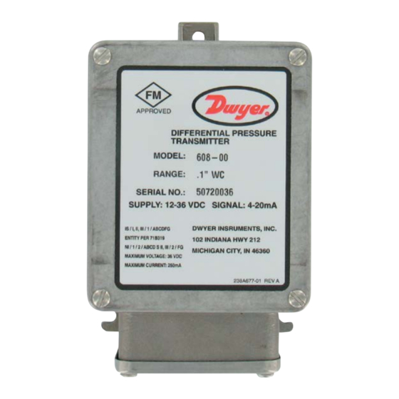
Series 608 Differential Pressure Transmitter
Specifications - Installation and Operating Instructions
The SERIES 608 Differential Pressure Transmitter converts positive, negative
(vacuum), or differential pressures of clean, dry air or other non-conductive, non-
corrosive gases into a standard 2-wire, 4-20 mA output signal. Several factory
calibrated models are available with ranges from 0-0.1 (0-2.5 mm) in w.c. up to 0-25
(0-634.4 mm) in w.c. All models employ a variable capacitance transducer with a
micro-machined, ultra thin silicon diaphragm enabling precision measurement and
control of very low differential pressures while withstanding a high static working
pressure of 100 psig (6.89 bar). The Series 608 is FM approved intrinsically safe
for use in the specified hazardous locations when used with an approved intrinsic
safety barrier. It also features a NEMA 4X (IP65) enclosure that allows for indoor and
outdoor installations. This rugged housing design makes this transmitter ideal for use
in industrial and process plant environments.
INSTALLATION
1. Location: Select a clean location free of excess vibration where the temperature
of the unit will be between 0°F (-18°C) and 160°F (71°C). Distance from the
receiver is limited only by total loop resistance. See "Electrical Connections". The
tubing supplying pressure to the transmitter can be run practically any distance.
Long tubing lengths will not affect accuracy but response time will be increased
slightly.
2. Position: The Series 608 Transmitter is not position sensitive. However, it is
recommended that you avoid mounting with pressure connections pointing up
because of the chance of condensed moisture entering the interior. Moisture can
also be avoided by routing tubing with a low point just ahead of the transmitter.
3. Mounting: Attach to mounting surface with two #8 or #10 screws in the mounting
slots provided.
4. Pressure Connections: The 608 series transmitter is shipped with the "HIGH"
and "LOW" pressure ports plugged to avoid debris entering the unit. The plugs
should be left in place until the tubing and fittings are connected. For gage
pressures, connect positive (above atmospheric) pressure to the port marked
"HIGH" and vent the "LOW" port. To monitor vacuum, connect negative (vacuum)
pressure to port marked "LOW" and vent the "HIGH" port. For differential
pressure, connect the higher one to the "HIGH" port and the lower one to the
"LOW" port.
The two 1⁄4˝ NPT pressure connections should be sealed to the transducer housing
using teflon tape. The use of a dope-type sealant should not be used since it may
cause measurement errors because of outgassing.
DWYER INSTRUMENTS, LLC
P.O. BOX 373 • MICHIGAN CITY, INDIANA 46360, U.S.A.
1/4
[6.35]
4-1/2
[107.95]
2-11/16
[68.26]
5/8
[15.88]
3
[76.20]
SPECIFICATIONS
Service: Clean/dry air and compatible gases. Clean dry air/gases compatible with
aluminum, titanium, PBT, buna, silicone, glass, gold, silicone RTV and stainless
steel. Not for use with liquids.
Wetted Materials: Consult factory.
Accuracy: ±0.5% or ±0.25% full scale.
Stability: ±0.5% F.S./year.
Pressure Limits: 100 psig (6.89 bar); 15 psid (1.03 bar).
Temperature Limits: -20 to 185°F (-28 to 85°C).
Compensated Temperature Range: 0 to 160°F (-18 to 71°C).
Thermal Effect: 0.5% Accuracy: ±0.02% F.S./°F; 0.25% Accuracy: ±0.01% F.S./°F.
Power Requirements: 12-36 VDC (2-wire).
Output Signal: 4-20 mA DC.
Zero and Span Adustments: Potentiometers for zero and span.
Response Time: 250 ms.
Loop Resistance: DC: 0-1045 Ωs maximum.
Electrical Connections: Screw terminal: Two 1/2˝ female NPT conduit.
Process Connections: Two 1/4˝ female NPT.
Enclosure Rating: NEMA 4X (IP65).
Mounting Orientation: Not position sensitive.
Weight: 2 lb (0.9 kg).
Agency Approvals: FM approved intrinsically safe for use in Class I, Div. 1,
Groups A, B, C, D; Class II, Div. 1, Groups E, F, G; Class III, Div. 1 when wired with
approved intrinsically safe barrier. Entity parameters: Vmax= 36 VDC; Imax= 250
mA; CI=12 nF; LI=0 mH.
WARNING
Read before insstallation.
1. GENERAL: A failure resulting in injury or damage may be caused by excessive
overpressure, excessive vibration or pressure pulsation, excessive instrument
temperature, corrosion of the pressure containing parts, or other misuse. Consult
Dwyer Instruments, LLC before installing if there are any questions or concerns.
2. OVERPRESSURE: Pressure spikes in excess of the rated over-pressure capability
of the transducer may cause irreversible electrical and/or mechanical damage to
the pressure measuring and containing elements.
3. STATIC ELECTRICAL CHARGES: Any electrical device may be susceptible
to damage when exposed to static electrical charges. To avoid damage to the
transducer observe the following:
• Ground the body of the transducer BEFORE making any electrical connections.
• When disconnecting, remove the ground LAST!
Note: The shield and drain wire in the cable (if supplied) are not connected to the
transducer body, and are not a suitable ground.
Phone: 219-879-8000
Fax: 219-872-9057
Bulletin E-60
3-1/4
1-1/2
[82.55]
[38.10]
5-1/32
[127.79]
1/2 NPT
TYP 2
PLACES
www.dwyer-inst.com
e-mail: info@dwyermail.com
1/4 NPT
TYP 2
PLACES
Advertisement
Table of Contents

Related Manuals for Dwyer Instruments 608 Series


Summary of Contents for Dwyer Instruments 608 Series
- Page 1 Read before insstallation. slots provided. 4. Pressure Connections: The 608 series transmitter is shipped with the “HIGH” 1. GENERAL: A failure resulting in injury or damage may be caused by excessive and “LOW” pressure ports plugged to avoid debris entering the unit. The plugs overpressure, excessive vibration or pressure pulsation, excessive instrument should be left in place until the tubing and fittings are connected.
- Page 2 ELECTRICAL CONNECTION Load Limitations 4-20 mA Output Only Use in hazardous location: The Series 608 transmitter is FM approved intrinsically LOOP RESISTANCE () safe for use in hazardous locations. See specifications for details. Intrinsically safe approved devices require the use of an approved intrinsic safety barrier when applied 1250 in hazardous locations.
- Page 3 ZERO ADJUSTMENT Hazardous Area Specific Guidelines The zero adjustment for the transducer can be accessed by unscrewing the four 1. Do not open unit when energized. cover screws and removing the zero pot access cover. Once the cover is removed, 2.
- Page 4 ©Copyright 2022 Dwyer Instruments, LLC Printed in U.S.A. 10/22 FR# 443350-00 Rev. 3 DWYER INSTRUMENTS, LLC Phone: 219-879-8000 www.dwyer-inst.com P.O. BOX 373 • MICHIGAN CITY, INDIANA 46360, U.S.A. Fax: 219-872-9057 e-mail: info@dwyermail.com...
Need help?
Do you have a question about the 608 Series and is the answer not in the manual?
Questions and answers