Table of Contents
Advertisement
Quick Links
Advertisement
Table of Contents

Related Manuals for THORLABS PCS-6000 Series


Summary of Contents for THORLABS PCS-6000 Series
- Page 1 PCS-6000 Series Motorized Patch-Clamp Micromanipulator User Guide...
-
Page 2: Table Of Contents
PCS-6000 Series Motorized Patch-Clamp Micromanipulator Table of Contents Chapter 1 Warning Symbols Chapter 2 Introduction 2.1. Overview 2.2. Major Components 2.2.1. Micromanipulator Assembly 2.2.2. Axis Control Unit 2.2.3. Joystick 2.2.4. Control Unit Chapter 3 Description 3.1. Mechanisms of Motion 3.1.1. Coarse Motion 3.1.2. - Page 3 PCS-6000 Series Motorized Patch-Clamp Micromanipulator 4.4.3. Joystick and ACU Connections 4.5. Axis Control Unit 4.6. Joystick Chapter 5 Installation 5.1. Unpacking the Unit 5.2. Removing the Shipping Clips 5.3. Mounting the Manipulator 5.4. Connecting the Cables 5.5. Mounting a Headstage and Pipette Chapter 6 Operation 6.1.
- Page 4 PCS-6000 Series Motorized Patch-Clamp Micromanipulator 7.2. Adjusting the Friction of the ACU Knobs 7.3. Adjusting the Friction and Eliminating Lateral Play in the Manual Adjustment Knobs 7.4. Troubleshooting Chapter 8 Specifications Chapter 9 Regulatory 9.1. Waste Treatment is Your Own Responsibility 9.2.
-
Page 5: Chapter 1 Warning Symbols
Caution: Risk of Danger. Should this equipment be used in a manner not specified by Thorlabs, Inc., the protection provided by the equipment may be impaired. Always follow the operating instructions as indicated! IEC Class I Product: Use only the 3-prong AC power cord supplied with this equipment. -
Page 6: Chapter 2 Introduction
Burleigh PCS-6000 Series Motorized Patch-Clamp Micromanipulators from Thorlabs, Inc. are ultra-stable, high-resolution positioning systems designed for patch clamp recording. Thorlabs, Inc. has incorporated more than 20 years of experience and knowledge in piezoelectric actuators, precision mechanics, and electronic control to create a system that maximizes your research productivity. -
Page 7: Major Components
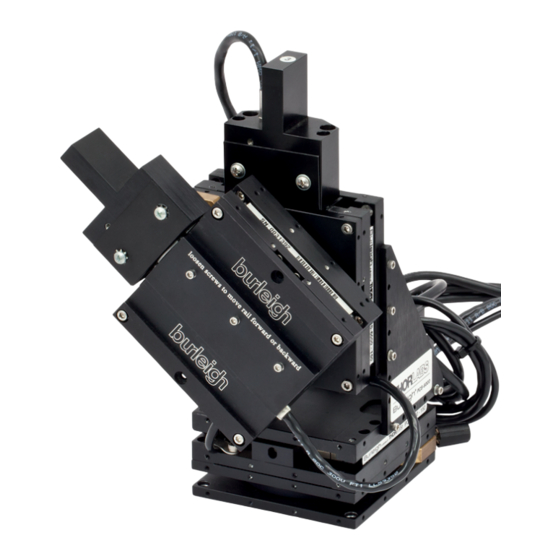
PCS-6000 Series Motorized Patch-Clamp Micromanipulator Chapter 2: Introduction 2.2. Major Components 2.2.1. Micromanipulator Assembly The micromanipulator assembly consists of up to four linear stages and two rotary pivot stages assembled with a 90° bracket. Depending on the configuration, the linear stages can have no piezo, a 150 μm piezo or a 300 μm piezo, no long-travel adjustment mechanism, a manual long... -
Page 8: Chapter 3 Description
PCS-6000 Series Motorized Patch-Clamp Micromanipulator Chapter 3: Description Chapter 3 Description 3.1. Mechanisms of Motion PCS-6000 linear stages integrate piezo-flexure assemblies inside crossed roller bearing linear stages with a stepping motor for coarse motion. The joystick is used to control the coarse motion. A large knob on the Axis Control Unit ( ACU) controls the fine positioning obtained by use of a piezo. -
Page 9: Configurations
PCS-6000 Series Motorized Patch-Clamp Micromanipulator Chapter 3: Description 3.2. Configurations The PCS-6000 is a modular system. Different configurations are available for the linear stages. Stages normally are configured with a motor and either 150 or 300 µm piezos. Alternatives to the normal configurations are those that have coarse motion provided by a manual adjusting screw or no coarse motion at all. - Page 10 PCS-6000 Series Motorized Patch-Clamp Micromanipulator Chapter 3: Description Axis 1 and Axis 2 have manual knobs only with no piezo elements and no motors. Axis 3 has a motor and a 150 μm piezo. It is available in both right and left handed configurations.
- Page 11 PCS-6000 Series Motorized Patch-Clamp Micromanipulator Chapter 3: Description PCS-6300 This configuration has three axes: ● Axis 1: Front to back ● Axis 3: Vertical ● Axis 4: Approach All three axes have motorized linear stages. Axis 1 and Axis 3 have 150 μm piezo elements while Axis 4 has 300 μm piezo elements.
- Page 12 PCS-6000 Series Motorized Patch-Clamp Micromanipulator Chapter 3: Description Figure 3–6 PCS-6400 PCS-6500 This configuration has four axes: ● Axis 1: Front to back ● Axis 2: Left to right ● Axis 3: Vertical ● Axis 4: Approach Axis 1 and Axis 2 have motorized linear stages only. Axis 3 has a motor and a 150 μm piezo element.
- Page 13 PCS-6000 Series Motorized Patch-Clamp Micromanipulator Chapter 3: Description Additional Configurations Non-standard configurations are available by special order from the factory. Their product designation is PCS6000 – (XXXX). Special order configurations permit the combination of options to suit the exact experiment. Coarse and fine positioning options are listed in the table below.
-
Page 14: Chapter 4 Orientation
PCS-6000 Series Motorized Patch-Clamp Micromanipulator Chapter 4: Orientation Chapter 4 Orientation 4.1. Control Unit The control unit supplies the drive signal to both the piezo actuators and the drive motors. The drive board for the motors is on the top layer. The drive board for the piezo actuators is on the bottom. -
Page 15: Servo Motor Control Memory Options
PCS-6000 Series Motorized Patch-Clamp Micromanipulator Chapter 4: Orientation Several configurations of the PCS-6000 have less than four motors. In these instances, there are unused motor receptacles that may be left untouched as they are inactive without the presence of a motor. -
Page 16: Rear Panel
PCS-6000 Series Motorized Patch-Clamp Micromanipulator Chapter 4: Orientation 4.4. Rear Panel Figure 4–2 Rear Panel of Control Unit 4.4.1. Operating Voltage The unit contains a universal power supply. No changes are needed to switch from 110V AC 60 Hz to another allowed voltage and frequency (For details see Chapter 8: Specifications). -
Page 17: Joystick
PCS-6000 Series Motorized Patch-Clamp Micromanipulator Chapter 4: Orientation Figure 4–3 Front View of Axis Control Unit There is a number on each face of the ACU that corresponds to the axis that the knob controls. The piezo cables from the manipulator should be plugged into the corresponding receptacle. - Page 18 PCS-6000 Series Motorized Patch-Clamp Micromanipulator Chapter 4: Orientation The joystick is used to control the servo motors to provide coarse positioning and has three axes of motion: front to back (X-axis), left to right (Y-axis) and rotat- ing the knob right to left (Z or approach axis).
-
Page 19: Chapter 5 Installation
PCS-6000 Series Motorized Patch-Clamp Micromanipulator Chapter 5: Installation Chapter 5 Installation 5.1. Unpacking the Unit Carefully unpack the unit and inspect for shipping damage. Severe damage to the packaging may indicate component damage. Notify your shipping/receiving department immediately. 5.2. Removing the Shipping Clips To prevent damage to the stages and piezo during shipment, the stage top and bottom are displaced from their normal positions with shipping clips. -
Page 20: Connecting The Cables
PCS-6000 Series Motorized Patch-Clamp Micromanipulator Chapter 5: Installation 2. If the mounting surface has a grid of 1/4-20 tapped holes, use the hardware provided to mount the rotation plate adapter to the mounting surface. 3. If the mounting surface has a grid of through holes or if a through hole... -
Page 21: Mounting A Headstage And Pipette
PCS-6000 Series Motorized Patch-Clamp Micromanipulator Chapter 5: Installation 6. Position the joystick and the ACU in a convenient location in the workstation. Plug the cables into the back of the control unit. The joystick and ACU are set up such that the cables from the units exit away from the operator. -
Page 22: Chapter 6 Operation
PCS-6000 Series Motorized Patch-Clamp Micromanipulator Chapter 6: Operation Chapter 6 Operation 6.1. Powering Up and Checking for Motor Motion 1. Plug in the AC line cord and turn on the control unit. After a second or two, the power indicators light on both the upper (motor) and lower (piezo) modules. -
Page 23: Adjusting The Approach Axis Angle
Chapter 6: Operation CAUTION Steep/Shallow headstage adapters shipped as part of the PCS-6000 series products require the addition of a spacer plate to allow full back and forth motion of the sliding dovetail. Consult Thorlabs, Inc. if the spacer plate is needed. -
Page 24: Setting The Adjustable Stop
PCS-6000 Series Motorized Patch-Clamp Micromanipulator Chapter 6: Operation 5. Holding the headstage to prevent it from slipping, loosen the headstage pivot knob. 6. Position the approach axis angles as desired, placing the pipette under the objective of the microscope. Carefully tighten the base pivot knob and headstage pivot knob until the stages are locked in position. -
Page 25: Operational Hints
6.5.4. Drift Problems Stability PCS-6000 series micromanipulators have the ability to hold the position of their stages to high precision. The performance specification is less than 1 µm per hour per axis. When the observed stability is not at this level many times there are a number of causes. -
Page 26: Chapter 7 Maintenance
PCS-6000 Series Motorized Patch-Clamp Micromanipulator Chapter 7: Maintenance Chapter 7 Maintenance 7.1. Overview of Maintenance Required 7.1.1. Maintenance Schedule PCS-6000 systems require a limited amount of routine maintenance. Items requiring periodic attention are listen below: Interval Between Service Item Comments... -
Page 27: Lubricating Motor Shafts
PCS-6000 Series Motorized Patch-Clamp Micromanipulator Chapter 7: Maintenance 7.1.2. Lubricating Motor Shafts 1. While the PCS-6000 is still electrically connected, align the stages as shown below. Figure 7–1 Align Stages Before Turning Off the Power 2. Remove the manipulator from the Faraday cage and place on a well-lit working space. - Page 28 PCS-6000 Series Motorized Patch-Clamp Micromanipulator Chapter 7: Maintenance Figure 7–3 Remove the Screw by Turning Counterclockwise 7. Apply lubricant to the screw. Only a small bead of lubricant is needed along the central 1" of the shaft. Figure 7–4 Apply Lubricant Along Central 1" Length of Motor Shaft 8.
- Page 29 PCS-6000 Series Motorized Patch-Clamp Micromanipulator Chapter 7: Maintenance 10. Orient the anti-rotate pin as shown in Figure 7-7. 11. Locate the anti-rotate slot in the moveable stage. Figure 7–7 Location of the Anti-rotate Slot 12. Align the anti-rotate pin on the motor shaft to the slot and slide the motor module into the stage (taking care to maintain the pin in the slot).
-
Page 30: Electronic Maintenance
PCS-6000 Series Motorized Patch-Clamp Micromanipulator Chapter 7: Maintenance Figure 7–9 Carrycot Alignment of Pin in Slot (only bottom of pin is visible) Figure 7–10 15. If the alignment is correct, finish tightening the 4-40 screws that hold the motor module to the stage. -
Page 31: Replacing The Fuse(S)
PCS-6000 Series Motorized Patch-Clamp Micromanipulator Chapter 7: Maintenance 7.1.4. Replacing the Fuse(s) The unit is supplied with a dual line fuse holder. In the unlikely event the main power line fuse(s) has blown, it can be replaced. The fact that the main fuse may have been blown is evidenced by the lack of any indicator lights on the front of the control unit. -
Page 32: Adjusting The Friction And Eliminating Lateral Play In The Manual Adjustment Knobs
PCS-6000 Series Motorized Patch-Clamp Micromanipulator Chapter 7: Maintenance 4. Maintaining the pressure on the knob, tighten the lock screws. 5. Repeat steps 1-4 for the other control knobs. Figure 7–13 Adjusting the Friction of an ACU Knob 7.3. Adjusting the Friction and Eliminating Lateral Play in the... - Page 33 PCS-6000 Series Motorized Patch-Clamp Micromanipulator Chapter 7: Maintenance Figure 7–15 Locating the Catch Hole 2. Turn the wrench clockwise to tighten the sleeve and increase the friction. Repositioning the wrench underneath and turning counterclockwise loosens the sleeve, decreasing the friction of the adjustment knob. Do not loosen the sleeve all the way.
-
Page 34: Troubleshooting
PCS-6000 Series Motorized Patch-Clamp Micromanipulator Chapter 7: Maintenance 7.4. Troubleshooting Problem: Excess motion of pipette tip during manual adjustment Typical Symptoms: Excess or erratic motion of pipette tip Pipette sensitive to vibration "Losing" cells after making a seal Probable Causes... - Page 35 PCS-6000 Series Motorized Patch-Clamp Micromanipulator Chapter 7: Maintenance CAUTION In cases where the PCS-6000 is not attached directly to the microscope, it is important that the microscope itself is stable. The microscope and the mount holding the PCS-6000 must both be rigidly attached to the same base plate or optical table.
- Page 36 PCS-6000 Series Motorized Patch-Clamp Micromanipulator Chapter 7: Maintenance Problem: No coarse motion Typical Symptoms: ● No motion is observed when joystick is activated. Probable Causes ● Motor may be running but end of travel has been reached and motor is in stall condition ●...
- Page 37 PCS-6000 Series Motorized Patch-Clamp Micromanipulator Chapter 7: Maintenance Problem: Drift Typical Symptoms: ● Pipette tip moving after manual and piezo adjustments are completed. ● "Losing" cells after making a seal. ♦ Also refer to the troubleshooting section, Problem: Excess Motion of Pipette Tip During Manual Adjustment, above.
-
Page 38: Chapter 8 Specifications
PCS-6000 Series Motorized Patch-Clamp Micromanipulator Chapter 8: Specifications Chapter 8 Specifications Environmental Specifications Operating Conditions Ambient Temperature 50 to 40 °C Altitude 2000 m maximum Atmospheric Pressure 70 to 106 kPa Relative Humidity 15 to 95% (non-condensing) Installation Category Pollution Degree... - Page 39 PCS-6000 Series Motorized Patch-Clamp Micromanipulator Chapter 8: Specifications PCS-6000 Series Specifications Performance Motorized 25 mm Manual 25 mm Travel Piezo 150 or 300 µm nominal nominal 60 nm (150 µm) OR 1.6 µm minimum step 32 threads per Resolution 120 nm (300 µm)
-
Page 40: Chapter 9 Regulatory
Waste Treatment is Your Own Responsibility If you do not return an “end of life” unit to Thorlabs, you must hand it to a com- pany specialized in waste recovery. Do not dispose of the unit in a litter bin or at a public waste disposal site. -
Page 41: Chapter 10 Warranty
Thorlabs, Inc. per- sonnel. The liability of Thorlabs, Inc. (except as to title) arising out of supplying of said product, or its use, whether under the foregoing warranty, a claim of negligence, or otherwise, shall not in any case exceed the cost of correcting defects in the products as herein provided. -
Page 42: Chapter 11 Contacts
PCS-6000 Series Motorized Patch-Clamp Micromanipulator Chapter 11: Contacts Chapter 11 Contacts For technical support or sales inquiries, please visit us at www.thorlabs.com/contact for our most up-to-date contact information. USA, Canada, and South America UK and Ireland Thorlabs, Inc. Thorlabs Ltd. - Page 43 www.thorlabs.com...
Need help?
Do you have a question about the PCS-6000 Series and is the answer not in the manual?
Questions and answers