
Subscribe to Our Youtube Channel
Related Manuals for Black Box JPM260


Summary of Contents for Black Box JPM260
- Page 1 © Copyright 2001. Black Box Corporation. All rights reserved. 1000 Park Drive • Lawrence, PA 15055-1018 • 724-746-5500 • Fax 724-746-0746...
- Page 2 Order toll-free in the U.S.: Call 877-877-BBOX (outside U.S. call 724-746-5500) FREE technical support 24 hours a day, 7 days a week: Call 724-746-5500 or fax 724-746-0746 SUPPORT Mailing address: Black Box Corporation, 1000 Park Drive, Lawrence, PA 15055-1018 INFORMATION Web site: www.blackbox.com • E-mail: info@blackbox.com...
- Page 3 FCC INFORMATION FEDERAL COMMUNICATIONS COMMISSION INDUSTRY CANADA RADIO FREQUENCY INTERFERENCE STATEMENTS This equipment generates, uses, and can radiate radio frequency energy and if not installed and used properly, that is, in strict accordance with the manufacturer’s instructions, may cause interference to radio communication.
- Page 4 RS-232 AND V.35 STANDARD PATCH PANELS INSTRUCCIONES DE SEGURIDAD (Normas Oficiales Mexicanas Electrical Safety Statement) 1. Todas las instrucciones de seguridad y operación deberán ser leídas antes de que el aparato eléctrico sea operado. 2. Las instrucciones de seguridad y operación deberán ser guardadas para referencia futura. 3.
- Page 5 TRADEMARKS USED IN THIS MANUAL TRADEMARKS USED IN THIS MANUAL Any trademarks mentioned in this manual are acknowledged to be the property of the trademark owners.
-
Page 6: Table Of Contents
RS-232 AND V.35 STANDARD PATCH PANELS Contents Chapter Page 1. Specifications ..............6 2. -
Page 7: Chapter Page
9.1 Calling Black Box ........ -
Page 8: Specifications
Power—JPM260, JPM265: 110 VAC; JPM261E, JPM266E: 220 VAC Size—JPM260, JPM261E: 5.25"H x 19"W x 5"D (13.3 x 48.3 x 12.7 cm); JPM265, JPM266E: 5.25"H x 19"W x 7"D (13.3 x 48.3 x 17.8 cm); JPM262, JPM263, JPM264, JPM267, JPM268, JPM269: 5.25"H x 29/32"W x 5"D (13.4 x 2.3 x 12.7 cm) -
Page 9: Introduction
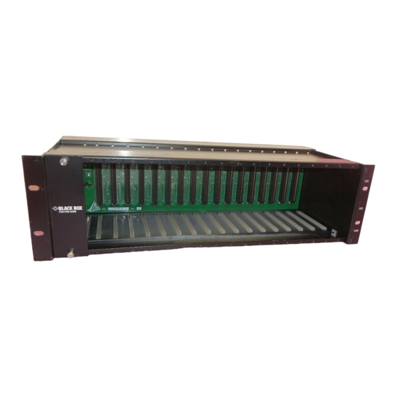
Depending on the system’s configuration, the Standard Patch Panel may include the following parts: rack chassis, test modules, patch modules, blank panel, power supply, this users’ manual, and accessories. 2.2.1 R HASSIS JPM260 RS-232 Standard Patch Panel Chassis with 110-VAC power supply JPM261E RS-232 Standard Patch Panel Chassis with 220-VAC power supply JPM265 V.35 Standard Patch Panel Chassis with 110-VAC power supply... -
Page 10: Blank Panel
JPM270 Blank Panel 2.2.6 A CCESSORIES You’ll also need patch cords and test patch cords (part number JPM258 [2-ft.] or JPM259 [6-ft.]). For details, call Black Box Technical Support at 724-746-5500. 2.3 Hardware Summary 2.3.1 F RONT HASSIS Identifying Modules The leftmost slot in the chassis is the only slot capable of using a test module. -
Page 11: Rear Chassis
CHAPTER 2: Introduction Figure 2-2. Identifying patch cavities. 2.3.2 R HASSIS The Standard Patch Panel’s rear chassis layout can include two configurations: DB25 male/female or M/34 male/female. DB25 male/female The DB25 male/female configuration corresponds to the RS-232 compliant chassis. In this configuration, the rear of the chassis consists of: (16) DB25 male DCE ports, (16) DB25 female DTE ports, (1) DB25 female test equipment port, (1) DB25 female control/converter port (reserved for future use), (1) 110/220 VAC jack, and (1) -48 VDC jack (for optional -48 VDC power supply). -
Page 12: Test Modules
RS-232 AND V.35 STANDARD PATCH PANELS M/34 male/female The M/34 male/female configuration corresponds to the V.35 compliant chassis only. In this configuration, the rear of the chassis consists of: (16) M/34 male DCE ports, (16) M/34 female DTE ports, (1) DB25 female test equipment port, (1) DB25 female control/converter port (reserved for future use), (1) 110/220 VAC jack, and (1) -48 VDC jack (for optional -48 VDC power supply). - Page 13 CHAPTER 2: Introduction RS-232 Test Module The RS-232 compliant test module is labeled JPM264. Figure 2-6 illustrates the elements found on the front panel. Figure 2-6. RS-232 test module.
- Page 14 RS-232 AND V.35 STANDARD PATCH PANELS V.35 Test Module Figure 2-7 illustrates the front panel of the V.35 compliant test module (JPM269). Figure 2-7. V.35 test module.
-
Page 15: Patch Modules
CHAPTER 2: Introduction 2.3.4 P ATCH ODULES All patch modules allow for the same signal pathways. Figure 2-8 illustrates the signal pathways for all patch modules. Figure 2-8. Patch modules signal pathways. - Page 16 RS-232 AND V.35 STANDARD PATCH PANELS Patch Module Elements The RS-232 and V.35 compliant patch modules are identical in appearance from the front side. The following picture shows the front panel. RTS Request to Send LED Figure 2-9. Front panel of the patch modules.
-
Page 17: Access Modules
CHAPTER 2: Introduction 2.3.5 A CCESS ODULES The Standard Access Module is used mainly for connecting a tester that doesn’t have patch capability. It allows the patch in the front to go directly to the DB connectors on the back of the chassis. 2.3.6 P OWER UPPLY... -
Page 18: Software Summary
RS-232 AND V.35 STANDARD PATCH PANELS 220-VAC power supply Figure 2-11. 220-VAC power supply. 2.4 Software Summary The Standard Patch Panel does not require software. -
Page 19: Installation
3. Installation 3.1 Inspecting the Standard Patch Panel Check the unit for possible damage. If anything is missing or damaged, call Black Box at 724-746-5500. 3.2 Mounting the Standard Patch Panel Consider these factors when mounting the Patch Panel: site environmental recommendations, rack mounting specifications, and chassis mounting procedure. -
Page 20: Adding And Removing Modules
RS-232 AND V.35 STANDARD PATCH PANELS 3.3 Adding and Removing Modules All Standard Patch Panel modules are hot-swappable. You do not have to power down to add or remove a module. Adding or removing a module will not cause an interruption in service. WARNING Always follow anti-static procedures when adding or removing a module. -
Page 21: Connecting External Test Equipment
CHAPTER 3: Installation 3.4 Connecting External Test Equipment The right rear of the Standard Patch Panel chassis includes a DB25 female port labeled “TEST EQUIP” that facilitates a connection to external test equipment. This port interfaces with the test module. The following diagram below illustrates how external test equipment connects to the Patch Panel chassis. - Page 22 RS-232 AND V.35 STANDARD PATCH PANELS Figure 3-3. Power connection (110 VAC). NOTE The Standard Patch Panel chassis has a port labeled “48V IN,” which is used for an optional internal -48 VDC power supply. ERFORMING A To check the function of the LEDs: 1.
-
Page 23: Labeling The Modules
2. If all the test and patch module LEDs do not light, recheck the power connections and the seating of the modules. 3. Perform the lamp test again. 4. If all of the test module and patch module LEDs still do not light, call Black Box Technical Support at 724-746-5500 for assistance. 3.6 Labeling the Modules We recommend that you label the front of each patch module with a number for easy reference. -
Page 24: Monitoring
RS-232 AND V.35 STANDARD PATCH PANELS 4. Monitoring 4.1 Monitoring a Patch Module from a Test Module When monitoring a patch module from a test module, you can use the test module to monitor the patch module alone. Or, you can connect the test module to external test equipment. When you do this, you can monitor the patch module with both the test module and the external test equipment. -
Page 25: Monitoring A Patch Module From External Test Equipment
CHAPTER 4: Monitoring Signal Pathway NOTE The contacts connecting the DCE and the DTE paths in the patch module are closed. Figure 4-2. Signal pathway. 4.2 Monitoring a Patch Module from External Test Equipment When monitoring a patch module from external test equipment, you can use the external test equipment alone to monitor a patch module. - Page 26 RS-232 AND V.35 STANDARD PATCH PANELS To monitor a patch module from external test equipment: 1. Connect one end of a test patch cord to the test module’s MON patch cavity. 2. Connect the opposite end of the same test patch cord to the external test equipment (see Figure 4-3). XAMPLE OF ONITORING FROM XTERNAL...
- Page 27 CHAPTER 4: Monitoring Signal Path NOTE The contacts connecting the DCE and the DTE paths in the patch module are closed. Patch Module LEDs DTE Patch Cavity DTE Interface DCE Patch Cavity DCE Interface MON Patch Cavity Test Cord Test Equipment Figure 4-4.
-
Page 28: Cross-Connecting
RS-232 AND V.35 STANDARD PATCH PANELS 5. Cross-Connecting Cross-Connecting Between DCE and DTE When cross-connecting a patch module to another patch module, you can monitor the patch module’s DCE signals through its MON patch cavity. See Chapter 4 for more information. You CANNOT monitor the patch module’s DTE signals through its MON patch cavity. - Page 29 CHAPTER 5: Cross-Connecting Signal Path NOTE The contacts connecting the DCE and DTE pathway in the patch modules are open. Figure 5-2. DCE to DTE signal pathway.
-
Page 30: Intrusive Testing
RS-232 AND V.35 STANDARD PATCH PANELS 6. Intrusive Testing Performing intrusive testing (a) breaks a patch module’s DCE to DTE signal pathway, (b) routes the DCE or DTE signal to the test module, to external test equipment, or both, and (c) permits interactive testing of the DCE or DTE signals. - Page 31 CHAPTER 6: Intrusive Testing Patch-Cord Connection Shown below is the patch cord connected to the test module MON and the patch module 2 DCE patch cavities. Figure 6-1. Patch-cord connection.
-
Page 32: External Test Equipment To Dce
RS-232 AND V.35 STANDARD PATCH PANELS DCE Signal Pathway NOTE The contacts connecting the DCE and DTE paths in the patch module are open. Figure 6-2. DCE signal pathway. 6.1.2 E XTERNAL QUIPMENT TO To connect an intrusive test from external test equipment to a patch module’s DCE: 1. - Page 33 CHAPTER 6: Intrusive Testing Example of Monitoring from a Test Module In this example, the external test equipment is connected, via a patch cord, to patch module 2’s DCE patch cavity. This permits the interactive testing of signals passing through patch module 2’s DCE. Patch-Cord Connection Shown below is the test patch cord connected to the external test equipment and the patch module 2 DCE patch cavity.
- Page 34 RS-232 AND V.35 STANDARD PATCH PANELS DCE Signal Pathway NOTE The contacts connecting the DCE and the DTE pathways in the patch module are open. Patch Module LEDs DTE Patch Cavity DTE Interface DCE Patch Cavity DCE Interface MON Patch Cavity Test Cord Test Equipment Figure 6-4.
-
Page 35: Intrusive Testing To A Patch Module Dte
CHAPTER 6: Intrusive Testing 6.2 Intrusive Testing to a Patch Module DTE During an intrusive test to a patch module DTE, you can monitor the patch module’s DCE signals through its MON patch cavity. See Chapter 4, Monitoring for more information. You cannot monitor the patch module’s DTE signals through its MON patch cavity. -
Page 36: External Test Equipment To Dte
RS-232 AND V.35 STANDARD PATCH PANELS DTE Signal Pathway NOTE The contacts connecting the DCE and DTE pathways in the patch module are open. Figure 6-6. DTE signal pathway. 6.2.2 E XTERNAL QUIPMENT TO To connect an intrusive test from external test equipment to a patch module’s DTE: 1. - Page 37 CHAPTER 6: Intrusive Testing Example of Monitoring from External Test Equipment In this example, the external test equipment is connected, via a patch cord, to patch module 2’s DTE patch cavity. This permits the interactive testing of signals passing through patch module 2’s DTE. Test Patch-Cord Connection TEST 4…...
- Page 38 RS-232 AND V.35 STANDARD PATCH PANELS DTE Signal Pathway NOTE The contacts connecting the DCE and DTE pathways in the patch module are open. Patch Module LEDs DTS Patch Cavity DTE Interface DCE Patch Cavity DCE Interface MON Patch Cavity Test Cord Test Equipment Figure 6-8.
-
Page 39: Using Test Points
CHAPTER 7: Using Test Points 7. Using Test Points You can use the test points found on the Standard Patch Panel test modules for non-interactive, non-intrusive monitoring of signals; interactive, intrusive testing of signals; or intrusive injecting of signals to test signal pathways. -
Page 40: Data Communication Interfaces
RS-232 AND V.35 STANDARD PATCH PANELS 8. Data Communication Interfaces Table 8-1. Data communication interfaces Patch RS-232 V.35 Cavity Signal DB25 Signal DB25 M/34 SD(A) RD(A) DCD(S) SCR(B) CTS(S) SD(B) SD(S) SCT(B) SCT(A) RD(S) RD(B) SCR(A) RTS(S) SCTE(B) SCTE SCTE(A) BUSY (S) = Secondary signal (A),(B) = Balanced pairs... -
Page 41: Troubleshooting
• Package it carefully. We recommend that you use the original container. • If you are shipping the Patch Panel for repair, make sure you include everything that came in the original package. Before you ship, contact Black Box to get a Return Material Authorization (RMA) number.
Need help?
Do you have a question about the JPM260 and is the answer not in the manual?
Questions and answers