
Subscribe to Our Youtube Channel
Related Manuals for Black Box JPM083A


Summary of Contents for Black Box JPM083A
- Page 1 © Copyright 1998. Black Box Corporation. All rights reserved. 1000 Park Drive • Lawrence, PA 15055-1018 • 724-746-5500 • Fax 724-746-0746...
-
Page 2: Customer Support Information
Order toll-free in the U.S. 24 hours, 7 A.M. Monday to midnight Friday: 877-877-BBOX FREE technical support, 24 hours a day, 7 days a week: Call 724-746-5500 or fax 724-746-0746 SUPPORT Mail order: Black Box Corporation, 1000 Park Drive, Lawrence, PA 15055-1018 INFORMATION Web site: www.blackbox.com • E-mail: info@blackbox.com... -
Page 3: Trademarks Used In This Manual
12- AND 24-PORT MODULAR PATCH PANELS TRADEMARKS USED IN THIS MANUAL UL is a registered trademark of Underwriters Laboratories Incorporated. Any other trademarks mentioned in this manual are acknowledged to be the property of the trademark owners. -
Page 4: Specifications
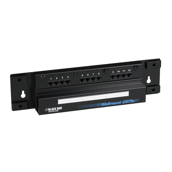
Temperature — Operating: 14 to 140°F (-10 to +60°C); Storage: -40 to +158°F (-40 to +70°C); 70% relative humidity Size — JPM083A, JPM084A: 4.2"H x 17.8"W x 2.8"D (10.7 x 45.2 x 7.1 cm); JPM085A, JPM086A: 8.2"H x 17.8"W x 2.8"D (20.8 x 45.2 x 7.1 cm) - Page 5 12- AND 24-PORT MODULAR PATCH PANELS 2. Introduction 2.1 Description The 12- and 24-Port Modular Patch Panels are designed for small- to medium-sized cross-connect applications where space is limited. For example, the Patch Panel is ideal for cluttered telecommuni- cation closets where relay racks aren’t practical. Because the Panel mounts directly on the wall, no extra rack equipment is needed.
- Page 6 12- AND 24-PORT MODULAR PATCH PANELS Removable, unobstructed designation strips Removable cover protects terminations Built-in Category jumper management Separate fields for terminating, patching J-12 J-13 J-18 J-19 J-24 Category Silk-screened jack and Built-in wire management block identification helps eliminate cable stress, maintain proper bend radius Figure 1.
-
Page 7: Installation
12- AND 24-PORT MODULAR PATCH PANELS 3. Installation Determine the appropriate mounting location for the patch panel. Insert screws (not supplied) through the keyholes in the rear panel and fasten the patch panel securely to the wall. There are countless ways to install cable in your patch panel. Figures 2 and 3 show (1) the suggested order to terminate the 110 clips (left side of the panel) and (2) the suggested routing of line cords between panels. - Page 8 12- AND 24-PORT MODULAR PATCH PANELS J-12 J-13 J-18 J-19 J-24 Category 2.00" J-12 3.84" 8.27" J-13 J-18 3.84" J-19 J-24 Category 14.31" 15.63" 17.75" Figure 2. Suggested Cable Installation for the 24-Port Patch Panels.
- Page 9 12- AND 24-PORT MODULAR PATCH PANELS The numbers in the diagram below The illustration below shows the illustrate the suggested order to suggested routing for line cords. terminate 110 clips. J-12 J-16 Figure 3. Suggested Cable Installation for the 12-Port Patch Panels.
Need help?
Do you have a question about the JPM083A and is the answer not in the manual?
Questions and answers