Table of Contents
Advertisement
Quick Links
LB0010A-A24-R2 LB0010A-A36-R2
LB0010A-U24-R2 LB0010A-U36-R2
LB0010A-A35-R2 LB0010A-A530-R2 LB0010A-A4W-R2 LB0010A-ASST-R2
LB0010A-U35-R2 LB0010A-U530-R2 LB0010A-U4W-R2 LB0010A-USST-R2
Remote MiniBridge
CUSTOMER SUPPORT INFORMATION
Order toll-free in the U.S.: Call 877-877-BBOX (outside U.S. call 724-746-5500)
FREE technical support 24 hours a day, 7 days a week: Call 724-746-5500 or fax 724-746-0746
Mailing address: Black Box Corporation, 1000 Park Drive, Lawrence, PA 15055-1018
Web site: www.blackbox.com • E-mail: info@blackbox.com
LB0010A-A21-R2 LB0010A-AMST-R2
LB0010A-U21-R2 LB0010A-UMST-R2
MARCH 1999
Advertisement
Table of Contents

Related Manuals for Black Box LB0010A-A24-R2


Summary of Contents for Black Box LB0010A-A24-R2
- Page 1 Order toll-free in the U.S.: Call 877-877-BBOX (outside U.S. call 724-746-5500) FREE technical support 24 hours a day, 7 days a week: Call 724-746-5500 or fax 724-746-0746 Mailing address: Black Box Corporation, 1000 Park Drive, Lawrence, PA 15055-1018 Web site: www.blackbox.com • E-mail: info@blackbox.com...
- Page 2 FCC AND IC STATEMENTS FEDERAL COMMUNICATIONS COMMISSION INDUSTRY CANADA RADIO-FREQUENCY INTERFERENCE STATEMENTS This equipment generates, uses, and can radiate radio frequency energy and if not installed and used properly, that is, in strict accordance with the manufacturer’s instructions, may cause interference to radio communication. It has been tested and found to comply with the limits for a Class A computing device in accordance with the specifications in Subpart J of Part 15 of FCC rules, which are designed to provide reasonable protection against such interference...
- Page 3 REMOTE MINIBRIDGE EUROPEAN UNION DECLARATION OF CONFORMITY The manufacturer declares that the Remote Minibridge conforms to the following standards: • EN55022 (1994): Limits and methods of measurement of radio disturbance characteristics of information technology equipment. • EN50082-1 (1992): Electromagnetic compatibility: Generic immunity standard for residential, commercial, and light industry.
- Page 4 NOM STATEMENT NORMAS OFICIALES MEXICANAS (NOM) ELECTRICAL SAFETY STATEMENT INSTRUCCIONES DE SEGURIDAD 1. Todas las instrucciones de seguridad y operación deberán ser leídas antes de que el aparato eléctrico sea operado. 2. Las instrucciones de seguridad y operación deberán ser guardadas para referencia futura.
- Page 5 REMOTE MINIBRIDGE 10. El equipo eléctrico deber ser situado fuera del alcance de fuentes de calor como radiadores, registros de calor, estufas u otros aparatos (incluyendo amplificadores) que producen calor. 11. El aparato eléctrico deberá ser connectado a una fuente de poder sólo del tipo descrito en el instructivo de operación, o como se indique en el aparato.
- Page 6 UL STATEMENTS UL Listing Requirements IMPORTANT SAFETY INSTRUCTIONS For North American Users The Remote MiniBridge is powered by an external power supply. To reduce the risk of shock, fire, and injury, use it only with a UL ® listed and CSA Certified Class 2 power supply rated 12 VDC, 400 or more mA.
- Page 7 REMOTE MINIBRIDGE TÜV Certification Requirements European Users Electrical ratings: 12 VDC, 400 or more mA CAUTION! To reduce the risk of electric shock, fire, and injury, use only with a power supply which is approved for the latest version of EN 60950. TÜV-Zertifizierungsanforderungen Europäische Benutzer Leistungsaufnahme: 12 VDC, 400 oder mehr mA...
-
Page 8: Table Of Contents
X.21 Models ........ 22 3.3.3 Fiberoptic Models ......23 3.3.4 Four-Wire Models ......23 3.4 Power ............26 4. Operation ............27 5. Troubleshooting ..........28 5.1 Calling Black Box ........28 5.2 Shipping and Packaging ......29 Appendix: WAN Pinouts ........30... -
Page 9: Specifications
REMOTE MINIBRIDGE 1. Specifications Compliance — CE; FCC Class A, IC Class/classe A Standards — LAN: IEEE 802.3 Ethernet v. 2 Interfaces — LAN: “-Axx” models: 10BASE5 AUI; “-Uxx” models: 10BASE-T; WAN: “-x24” models: TIA RS-232/ITU-TSS V.24/V.28, DTE; “-x35” models: ITU-TSS V.35; “-x36”... - Page 10 CHAPTER 1: Specifications Buffer Size — 256 frames Throughput Delay — 1 frame Data Format — WAN: HDLC-like frames (in async mode, these are broken into 8-data-bit octets which are preceded by a start bit and followed by a stop bit) Flow Control —...
- Page 11 REMOTE MINIBRIDGE Fiber Specifications (Fiberoptic Models Only) — Optical output power: “-xMST” models: –18 dBm into 62.5/125 µm fiber; “-xSST” models: –18 dBm into 9/125 µm fiber; Receiver sensitivity: –32.5 dBm; Dynamic Range: 20.5 dBm minimum; Maximum Distance — LAN: AUI models: 50 m (164 ft.) to attached device;...
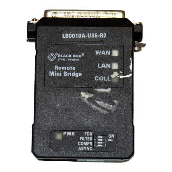
- Page 12 CHAPTER 1: Specifications Indicators — (4) Top-mounted LEDs: WAN (lights yellow in response to WAN data activity), LAN (all models: lights yellow in response to LAN data activity; 10BASE-T models: lights green to show link integrity), COLL (lights red in response to LAN collision), and PWR (lights green while unit is powered) Connectors —...
- Page 13 REMOTE MINIBRIDGE CAUTION! Although the Remote MiniBridge can operate on any regulated 12-VDC power supply that provides at least 400 mA of current, using a different power supply from the one the unit came with will void CE compliance for the 4-wire and fiberoptic models.
- Page 14 CHAPTER 1: Specifications Weight — Fiberoptic models: 1.6 oz. (50 g); All other models: 1 oz. (30 g)
-
Page 15: Introduction
REMOTE MINIBRIDGE 2. Introduction The Remote MiniBridge (RMB) is a high-performance, remote, self-learning Ethernet bridge. Its small size and low cost make it ideal for cost-sensitive bridging applications, as well as for LAN-extender or segmenter applications. The RMB automatically learns MAC addresses on the LAN to which it is connected and only forwards frames destined for another LAN. -
Page 16: Lan-Interface Overview
CHAPTER 2: Introduction 2.1 LAN-Interface Overview The Remote MiniBridge comes in either of two LAN interfaces: 10BASE-T or 10BASE5 (AUI) Ethernet. 10BASE-T models can operate in full-duplex Ethernet (20 Mbps). AUI models can’t do this, but they can draw power directly from the AUI interface, so you might not need to use an external power source. - Page 17 REMOTE MINIBRIDGE asynchronously at up to 115.2 Kbps if you tie some of the unit’s DB25 pins to ground (see Table 2-1 below). The RMB can internally generate seven standard asynchron- ous frequencies (9.6, 14.4, 19.2, 28.8, 38.4, 57.6, and 115.2 Kbps), or it can derive a different asynchronous data rate by dividing by sixteen the frequency of a sync signal on Pin 15.
- Page 18 CHAPTER 2: Introduction The Remote MiniBridge uses a variant of HDLC framing for WAN communication, in accordance with RFC 1662. In asynchronous mode, the RMB breaks up the frames into 8-data-bit octets which are preceded by a start bit and followed by a stop bit. To make this process transparent (to achieve “frame transparency”), it normally uses “octet stuffing”—it replaces any flag sequence (0x7E), control-escape octet (0x7D), or other...
- Page 19 REMOTE MINIBRIDGE The RMB’s comprehensive LED display indicates LAN and WAN activity, link integrity (on 10BASE-T models), and power (see Chapter 4). The unit has four conveniently located DIP switches for easy configuration (see Section 3.1). A typical application for the Remote MiniBridge is shown in Figure 2-1 below.
-
Page 20: Installation
CHAPTER 3: Installation 3. Installation 3.1 Switch Setting Refer to Table 3-1 on the next page as you set the Remote MiniBridge’s top-mounted DIP switches. 3.2 LAN Interface If your Remote MiniBridge is an AUI model, either plug it directly into the DTE’s AUI port or attach it to the DTE’s AUI port with a standard AUI cable. - Page 21 REMOTE MINIBRIDGE Table 3-1. Switch Settings Name (Default Setting) Description FDX (OFF) Set to ON for full-duplex Ethernet. (on 10BASE-T models) Set to OFF for half-duplex Ethernet. NOTE: This setting has no effect on WAN communica- tion, which can always be simplex, half-duplex, or full-duplex (the RMB transparently auto-adjusts).
-
Page 22: Wan Interface
CHAPTER 3: Installation 3.3 WAN Interface 3.3.1 RS-232 RS-530 M ODELS If you are attaching the Remote MiniBridge to: • A DCE device with a DB25 male serial port: Securely plug the RMB’s DB25 female WAN connector directly into the device’s serial port. •... -
Page 23: V.35, Rs-449/V.36, Or X.21 Models
Call Black Box for technical support. Refer to the Appendix for the pinouts of the RMB’s WAN connector and of the included adapter cable. -
Page 24: Fiberoptic Models
CHAPTER 3: Installation 3.3.3 F IBEROPTIC ODELS Run duplex fiber cabling of the appropriate type (62.5/125 for multimode or 9/125 for single-mode) between your Remote MiniBridges. (Save the protective caps for the RMBs’ fiberoptic connectors in case you need to store or relocate the RMBs later.) Make sure that the TX connector on each RMB is attached to the RX connector on the other RMB. - Page 25 REMOTE MINIBRIDGE To connect a cable to either RMB, take these steps, referring to Figure 3-1 below: CAUTION! Do not apply power to the Remote MiniBridge until you finish this procedure. The RMB could be damaged and you could suffer a dangerous electrical shock. Terminal Block TX–...
- Page 26 CHAPTER 3: Installation 2. Strip off the last inch and a half or so of the cable’s outer jacket, then strip the last quarter of an inch or so of the component wires’ insulation. 3. Disconnect the RMB from any electrical power source, including the LAN interface.
-
Page 27: Power
REMOTE MINIBRIDGE 3.4 Power Once you’ve connected the LAN and WAN cables to the Remote MiniBridge, plug the output cable of the unit’s power supply into its power jack. (If your RMB is an AUI model, you might not need to use the external power supply;... -
Page 28: Operation
CHAPTER 4: Operation 4. Operation The Remote MiniBridge operates completely automatically. It gets its power from its external power supply or (optionally, if it’s an AUI model) from the AUI interface. During normal operation, the unit’s PWR LED is continuously lit. On 10BASE-T models, the green LAN LED should be continuously lit if the 10BASE-T link between the RMB and the attached device is OK. -
Page 29: Troubleshooting
5.1 Calling Black Box If your Remote MiniBridge seems to be malfunctioning, do not attempt to alter or repair the unit. It contains no user- serviceable parts. Call Black Box Technical Support at 724-746-5500; the problem might be solvable over the phone. -
Page 30: Shipping And Packaging
• Package it carefully. We recommend that you use the original container. • If the shipping is return- or repair-related, pack the RMB, its power supply, and this manual together. Contact Black Box to get a Return Materials Authorization (RMA) number. -
Page 31: Appendix: Wan Pinouts
REMOTE MINIBRIDGE Appendix: WAN Pinouts The DB25 WAN connector that most of the Remote MiniBridge models have is pinned out differently on different models of the RMB, depending on which WAN interface the model uses. RS-232 models use the normal TIA RS-232-C pinout shown in the “RS-232”... - Page 32 APPENDIX: WAN Pinouts function. (See Section 2.2.) Be aware that the X.21 and V.35 adapter cables do not patch through all of these leads, so some of them—the ones marked “N/A” instead of “n BAUDX” or “n ACCM” in the table’s X.21 and V.35 (M/34) columns—aren’t available on the adapter cable’s native X.21 and V.35 connectors.
- Page 33 REMOTE MINIBRIDGE...
- Page 34 APPENDIX: WAN Pinouts...
- Page 35 REMOTE MINIBRIDGE TRADEMARK USED IN THIS MANUAL ST is a registered trademark of AT&T. Any other trademarks mentioned in this manual are acknowledged to be the property of the trademark owners.
- Page 36 NOTES...
- Page 37 NOTES...
- Page 38 © Copyright 1999. Black Box Corporation. All rights reserved. 1000 Park Drive • Lawrence, PA 15055-1018 • 724-746-5500 • Fax 724-746-0746...
Need help?
Do you have a question about the LB0010A-A24-R2 and is the answer not in the manual?
Questions and answers