Table of Contents
Advertisement
Quick Links
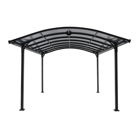
Model # GFM00725R
USE AND CARE GUIDE
STEEL AND ALUMINUM CARPORT
Questions, problems, missing parts? Before returning to the store
call Royal Garden Customer Service.
6 a.m. - 9 p.m., EST, 9 a.m. - 5 p.m., PST, Monday - Friday
(866) 988-3300
WWW.ROYALGARDEN.COM
THANK YOU
We appreciate the trust and con dence you have placed in Royal Garden through the purchase of this carport. We strive to continually create
quality products designed to enhance your home. Visit us online to see our full line of products available for your home improvement needs.
Thank you for choosing Royal Garden!
Advertisement
Table of Contents

Related Manuals for Royal garden GFM00725R


Summary of Contents for Royal garden GFM00725R
- Page 1 THANK YOU We appreciate the trust and con dence you have placed in Royal Garden through the purchase of this carport. We strive to continually create quality products designed to enhance your home. Visit us online to see our full line of products available for your home improvement needs.
-
Page 2: Table Of Contents
Table of Contents Table of Contents ............2 Pre-Assembly ..............3 Safety Information ............2 Planning Assembly ..............3 Hardware Included ..............3 Product Caution ..............2 Safety Warnings ..............2 Package Contents..............4 Carport Assembly ............6 Warranty ................ 2 Care and Cleaning ............ -
Page 3: Pre-Assembly
Pre-Assembly PLANNING ASSEMBLY Read all instructions before assembly. To avoid damaging this product, assemble it on a soft, non-abrasive surface such as carpet or cardboard. NOTE: More than one person may be required to assemble this product. HARDWARE INCLUDED NOTE: Hardware not shown to actual size. Part Description Quantity... -
Page 4: Package Contents
Pre-Assembly (continued) PACKAGE CONTENTS N L2 H L1... - Page 5 Pre-Assembly (continued) PACKAGE CONTENTS Part Description Quantity Right pillar Left pillar Middle pillar Left beam Right beam Right drain-pipe Left drain-pipe Side top tube A Side top tube B Top tube A Top tube B Light tube A Light tube B Top horizontal tube Left drain-pipe plastic part Right drain-pipe plastic part...
-
Page 6: Carport Assembly
Assembly ATTACHING THE PILLAR BASE PLATES AND PILLAR BASE CAPS TO THE PILLARS Attach the pillar base caps (T) and pillar base plates (S) to the right pillars (A1) using M6X15 combination bolts (CC), as shown below. Repeat this step for the left pillars (A2) and middle pillars (A3). Once all of the bolts are in place, fully tighten the bolts. - Page 7 Assembly (continued) ATTACHING THE LEFT BEAM AND THE RIGHT BEAM Lay the left beam (B1) and the right beam (B2) down on a soft surface. Connect the left beam (B1) and the right beam (B2) with the Alum. Liner pipe (U). Secure the left beam (B1) and the right beam (B2) using M8x25 combination bolts (EE), as shown below.
- Page 8 Assembly (continued) ATTACHING THE LIGHT TUBES Lay the light tube A (E1) and the light tube B (E2) down on a soft surface. Connect the light tube A (E1) and the light tube B (E2) with the top tube liner (M), and join the plugs together (see gure 3-1, 3-2). Secure the light tube A (E1) and the light tube B (E2) using M6X15 combination bolts (CC), as shown below (see gure 3-3).
- Page 9 Assembly (continued) ATTACHING THE TOP TUBES TO THE BEAMS AND THE LIGHT TUBES Put the assembled left beam (B1) and the right beam (B2) on each side, the light tube A (E1) and the light tube B (E2) in the middle, as shown below.
- Page 10 Assembly (continued) ATTACHING THE TOP SUPPORT PARTS TO THE TOP TUBES A Attach the top support parts (O2) to the top tubes A (D3) using M8x60 combination bolts (GG), M8 washers (II) and M8 nuts (JJ), as shown below. Once all of the bolts are in place, fully tighten the bolts. E1 &...
- Page 11 Assembly (continued) ATTACHING THE TOP SUPPORT PART AND INDUCTION MASK TO THE TOP TUBES A Put the top support part and induction mask (O1) under the top tubes A (D3). Join the plugs of the top support part and induction mask (O1) and the light tube A (E1), as shown below. Attach the top support part and induction mask (O1) to the top tubes A (D3) using M8X60 combination bolts (GG), M8 washers (II) and M8 nuts (JJ), as shown below.
- Page 12 Assembly (continued) ATTACHING THE TOP TUBE B TO THE BEAMS AND THE LIGHT TUBES Attach the top tubes B (D4) to the assembled left beams (B1) and right beams (B2) using M6X65 combination bolts (DD). Attach the top tubes B (D4) to the assembled light tube A (E1) and light tube B (E2) using M6X15 combination bolts (CC). Once all of the bolts are in place, fully tighten the bolts.
- Page 13 Assembly (continued) ATTACHING THE SIDE TOP TUBES TO THE BEAMS AND THE LIGHT TUBES Attach the side top tubes (D1 & D2) to the assembled left beams (B1) and right beams (B2) using M6X65 combination bolts (DD). Attach the side top tubes (D1 & D2) to the assembled light tube A (E1) and light tube B (E2) using M6X15 combination bolts (CC). Once all of the bolts are in place, fully tighten the bolts.
- Page 14 Assembly (continued) ATTACHING THE TOP HORIZONTAL TUBES TO THE SIDE TOP TUBES AND THE TOP TUBES Attach the top horizontal tubes (F) to the side top tubes (D1 & D2) using M6X15 combination bolts (CC). Attach the top horizontal tubes (F) to the top tubes (D3 & D4) using M6X15 combination bolts (CC). Once all of the bolts are in place, fully tighten the bolts.
- Page 15 Assembly (continued) ATTACHING THE SOLAR RECEIVER Attach the solar receiver (J) above the light tube A (E1), join the plugs of the light tube A (E1) to the solar receiver (J), as shown below. Attach the solar receiver (J) to the light tube A (E1) using M6X15 combination bolts (CC), as shown below. Attach the top tube cover plates (I) to both sides of the light tube A (E1) and the light tube B (E2), as shown below.
- Page 16 Assembly (continued) ATTACHING THE PILLARS Attach the right pillar (A1) and the left pillar (A2) to the right beam (B2) and the left beam (B1) using M8X25 combination bolts (EE), as shown below. Attach the middle pillar (A3) to the left beam (B1) and the right beam (B2) using M8X25 combination bolt (EE) and (FF),as shown below. NOTE: Do not fully tighten the bolts by using wrench (KK).
- Page 17 Assembly (continued) ATTACHING THE SUPPORT CHIPS Attach the support chip 1 (Q) to the right pillar (A1) and the left pillar (A2) using M8X90 combination bolt (HH), M8 washer (II) and M8 nut (JJ); attach the support chip 1 (Q) to the left beam (B1) and the right beam (B2) using M8X90 combination bolt (HH), M8X55 combination bolt (FF), M8 washers (II) and M8 nuts (JJ), as shown below.
- Page 18 Assembly (continued) ATTACHING THE PILLARS Attach the right pillar (A1) and the left pillar (A2) to the left beam (B1) and the right beam (B2) using M8X25 combination bolts (EE), as shown below. Attach the middle pillar (A3) to the left beam (B1) and the right beam (B2) using M8X25 combination bolt (EE) and (FF), as shown below. NOTE: Do not fully tighten the bolts by using wrench (KK).
- Page 19 Assembly (continued) ATTACHING THE SUPPORT CHIPS Attach the support chip 1 (Q) to the right pillar (A1) and the left pillar (A2) using M8X90 combination bolts (HH), M8 washers (II) and M8 nut (JJ); attach the support chip 1 (Q) to the left beam (B1) and right beam (B2) using M8X90 combination bolt (HH), M8 washer (II) and M8 nut (JJ), M8X55 combination bolt (FF), M8 washer (II) and M8 nut (JJ), as shown below.
- Page 20 Assembly (continued) ATTACHING THE SUN BOARD Tear off the thin film on sun board (V). Insert the sun board (V) through inclined side top tube A (D1), the side top tube B (D2), the top tubes A (D3), the top tube B (D4), as shown below. NOTE: More than one person is required to assemble this step and suggest using a stepladder.
- Page 21 Assembly (continued) ATTACHING THE TOP TUBE METAL PART TO TOP TUBE A AND TOP TUBE B Attach the top tube metal parts (P) to the both sides of the top tube A (D3), the top tube B (D4) using M6X15 combination bolts (CC), as shown below.
- Page 22 Assembly (continued) ATTACHING THE RIGHT DRAIN-PIPE, LEFT DRAIN-PIPE, LEAK-PROOF PART 1, LEAK-PROOF PART 2, MIDDLE DRAIN-PIPE PLASTIC PART AND U SHAPE PART Attach the leak-proof part 2 (L1) to the side without hole on right drain-pipe (C1) Attach the leak-proof part 1 (L2) to the side without hole on left drain-pipe (C2). Insert the U shape part (H) to the hole of middle drain-pipe plastic part (N), and then insert the U shape part (N) to the right drain-pipe (C1) and left drain-pipe (C2).
- Page 23 Assembly (continued) ATTACHING THE RIGHT DRAIN-PIPE, THE LEFT DRAIN-PIPE TO THE TOP TUBES Attach the assembled right drain-pipes (C1) and left drain-pipes (C2) to the top tube A (D3), and top tubes B (D4) using M6X15 combination bolts (CC). Attach the left drain-pipe plastic parts (G1) to the side of left drain-pipes (C2). Attach the right plastic parts (G2) to the side of right drain-pipes (C1).
-
Page 24: Care And Cleaning
Assembly (continued) SECURING THE PILLAR BASE PLATES TO THE GROUND Slightly lift up the pillar base caps (T). Use Dia.10 electric drill to drill the hole through the pillar base plates (S) to the ground. Drill vertically with the depth of about 70mm. Secure the pillar base plates (S) to the ground by using the M6x60 expansion screw s (LL). - Page 25 Questions, problems, missing parts? Before returning to the store call Royal Garden Customer Service. 6 a.m. - 9 p.m., EST, 9 a.m. - 5 p.m., PST, Monday - Friday (866) 988-3300 WWW.ROYALGARDEN.COM Retain this manual for future use.
Need help?
Do you have a question about the GFM00725R and is the answer not in the manual?
Questions and answers