Table of Contents
Advertisement
Available languages
Available languages
Quick Links
INSTRUCTION
EN
REGIO RC-DO
i
Read this instruction before installation
and wiring of the product
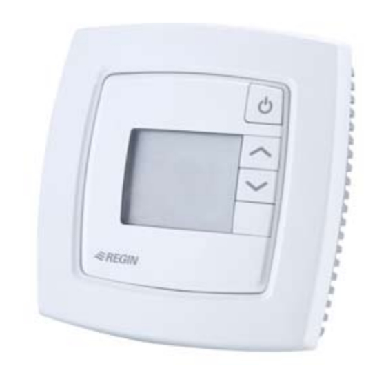
Room controller with display
RC-DO is a room controller from the Regio Mini series, intended to con-
trol heating and cooling in a zone control system. The controller has a
display. Installation is directly on the wall or on an electrical connection
box. The controller does not have a communication connection.
Technical data
Supply voltage
18...30 V AC, 50...60 Hz
Internal consumption
2.5 VA
Ambient temperature
0...50°C
Ambient humidity
Max 90% RH
Storage temperature
-20...+70°C
Display
LCD with background illumination
Built-in temperature sensor NTC Type, range 0...50°C,
accuracy +/-0.5°C at 15...30°C
Inputs
Refer to connection illustrations and
table below
terminal blocks
So-called lift type for cable cross-section
2.1 mm
2
Protection class
IP20
Material, casing
Polycarbonate, PC
Weight
110 g
Dimensions
95 x 95 x 28 mm
Occupancy button
INCREASE button
DECREASE button
Place the controller in a location that has a temperature representative for
the room. A suitable location is approx. 1.6 m above floor level in a place
with unobstructed air circulation.
Remove the frame by depressing the locking tab in the lower edge of the
cover with a screwdriver. See figure 1.
Then prize out the electronics cassette using the four rectangular screwdri-
ver slots and levering against the edge of the bottom plate. See figure 2.
Note: Take care not to damage the electronics when inserting the screw-
driver into the slots.
Figure 1
Figure 2
The bottom plate with terminals has a number of fixing hole combina-
tions. Select suitable holes (see figure 3) and screw the bottom plate onto
the wall or connection box, so that the arrows on the bottom plate point
upwards. Do not tighten the screws too hard!
With surface-mounted cabling, break-out suitable holes from the marks in
the plastic.
68
60
Figure 3. Bottom plate with mounting alternatives and location of
terminals (dimensions in mm.)
°C
30
AI1
G
10
31
UI1
G0
11
32
DI1
DO1
12
°C
33
DI2/CI
-
13
-
14
40
+C
GDO
20
41
AGnd
G0
21
42
-
-
22
43
-
UO1
23
UO2
24
Figure 4. Connection diagram for RC-DO
30
AI1
G
10
31
UI1
G0
11
32
DI1
DO1
12
33
DI2/CI
-
13
-
14
40
+C
GDO
20
41
AGnd
G0
21
42
-
-
22
43
-
UO1
23
UO2
24
Figure 5. Alternative connection for terminals 31, UI1, and terminal
33, DI2/CI, terminal 23, UO1, and terminal 24, UO2.
24 V AC
G0
G
G
G0
Y
G
G0
Y
Advertisement
Table of Contents

Related Manuals for Regin Regio Mini Series


Summary of Contents for Regin Regio Mini Series
- Page 1 Room controller with display RC-DO is a room controller from the Regio Mini series, intended to con- Figure 4. Connection diagram for RC-DO trol heating and cooling in a zone control system. The controller has a display.
- Page 2 23 and 20, GDO. RC-DO has an input for change-over that automatically resets the DI2/CI Regin’s condensation detector, KG-A (FS). The sen- output UO1 to operate with heating or cooling function. The input can Selection of output function, analogue or digital,...
- Page 3 Operating mode Display handling First the display will show the parameter-number 1. Scroll between There are five different operating modes. Switching between these parameters by using the INCREASE and DECREASE buttons. Indications modes is performed locally. Press the Occupancy button to select the desired parameter. The para- The display has the following indications: Stand-by: Both heating and cooling are disconnected within a tem- meter number will be replaced by the parameter value.
- Page 4 10 min Contact cupancy No function for this model AB Regin, Box 116, 428 22 Kållered, Sweden Switch on delay for occupancy 0 min Min. flow at cooling output with regulating Tel: +46 31 720 02 00, Fax: +46 31 720 02 50...
- Page 5 INSTRUKTION figur 2. OBS! Var försiktig så att du inte kommer åt elektroniken när du REGIO RC-DO °C sticker in mejseln i demonteringshålen. 24 V AC Läs denna instruktion innan produkten °C monteras och ansluts DI2/CI Rumsregulator med display AGnd RC-DO är en rumsregulator i Regio Mini-serien avsedd att styra värme och kyla i efterbehandlingssystem.
- Page 6 Värme/Kyla med VAV-reglering 24 V AC ut gemensam för DO. Internt förbunden För växling mellan värme och kyla i tvårörsystem Värme och kyla styrs på motsvarande sätt som i VAV-regleringen med plint 10, G. (Change-over). ovan. Det går dock inte att forcera spjället. Kylutgången har en PT1000-givare ansluts mellan plint 31 och 41, 0 V gemensam för UO.
- Page 7 Närvarodetektor Knappar Parameternummer För lokal styrning av driftläget mellan Förinställt driftläge och Bypass RC-DO har följande knappar: Följande parametrar är ändringsbara i parametermenyn: ansluts en närvarodetektor. • Närvaroknappen Para- Beskrivning Då man håller inne Närvaroknappen i mer än 5 sekunder ändrar meter- regulatorn driftläge till ”Shutdown”...
- Page 8 Minflöde på kylutgången då reglerfall värme/kyla med VAV-reglering är vald Kontakt Maxflöde på kylutgången då reglerfall AB Regin, Box 116, 428 22 Kållered värme/kyla med VAV-reglering är vald och Tel: +46 31 720 02 00, Fax: +46 31 720 02 50 värme styrs ut www.regin.se, info@regin.se...
Need help?
Do you have a question about the Regio Mini Series and is the answer not in the manual?
Questions and answers