Advertisement
Available languages
Available languages
Quick Links
INSTRUCTION
EN
REGIO RC-DFO
i
Read this instruction before installation
and wiring of the product
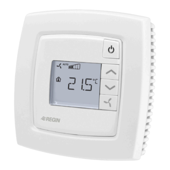
Room controller with fan switch and display
RC-DFO is a room controller from the Regio Mini series, intended to
control heating and cooling in a zone control system. It has a switch
for controlling a three-speed fan (fan coil), and a display. Installation is
directly on the wall or on an electrical connection box. The controller
does not have a communication connection.
Technical data
Supply voltage
18...30 V AC, 50...60 Hz
Internal consumption
2.5 VA
Ambient temperature
0...50°C
Ambient humidity
Max 90% RH
Storage temperature
-20...+70°C
Display
LCD with background illumination
Built-in temperature sensor NTC Type, range 0...50°C, accuracy
+/-0.5°C at 15...30°C
Inputs and outputs
Refer to connection illustrations and table
below
Connection terminals
Lift type for cable cross-section 2.1 mm
Protection class
IP20
Material, casing
Polycarbonate, PC
Weight
110 g
Dimensions
95 x 95 x 28 mm
Installation
Place the controller in a location that has a temperature representative for
the room. A suitable location is approx. 1.6 m above floor level in a place
with unobstructed air circulation.
Remove the frame by depressing the locking tab in the lower edge of the
cover with a screwdriver. See figure 1.
Then prize out the electronics cassette using the four rectangular screwdri-
ver slots and levering against the edge of the bottom plate. See figure 2.
Note: Take care not to damage the electronics when inserting the screw-
driver into the slots.
Figure 1
The bottom plate with terminals has a number of fixing hole combina-
tions. Select suitable holes (see figure 3) and screw the bottom plate onto
the wall or connection box, so that the arrows on the bottom plate point
upwards. Do not tighten the screws too hard!
With surface-mounted cabling, break-out suitable holes from the marks in
the plastic.
RC-DFO has digital outputs for control of a 3-speed fan. The relay module
RB3 can be used to handle fans with 230 V AC supply voltage. For more
information, see separate product sheet for RB3.
2
RC-DFO
Occupancy button
INCREASE button
DECREASE button
FAN button
°C
°C
Figure 4. Connection diagram for RC-DFO
Figure 2
10 11 12 13 14
20 21 22 23 24
UP
UP
68
60
30 31 32 33
40 41 42 43
Figure 3. Bottom plate with mounting alternatives and loca-
tion of terminals (dimensions in mm.)
30
AI1
G
10
24 V AC
31
UI1
G0
11
32
DI1
DO1
12
12
13
33
DI2/CI
DO2
13
14
DO3
14
20
40
+C
GDO
20
G
41
AGnd
G0
21
G0
Y
42
-
DO4
22
G
43
-
UO1
23
G0
UO2
24
Y
G
G0
30
AI1
G
10
31
UI1
G0
11
32
DI1
DO1
12
33
DI2/CI
DO2
13
DO3
14
40
+C
GDO
20
41
AGnd
G0
21
42
-
DO4
22
43
-
UO1
23
UO2
24
Figure 5. Alternative connection for terminals 31, UI1, and terminal
33, DI2/CI, terminal 23, UO1, and terminal 24, UO2.
L
RB3
30
I
31
II
M
N
32
III
33
1
Advertisement

Related Manuals for Regin REGIO RC-DFO


Summary of Contents for Regin REGIO RC-DFO
- Page 1 INSTRUCTION REGIO RC-DFO Occupancy button 10 11 12 13 14 20 21 22 23 24 INCREASE button DECREASE button FAN button 30 31 32 33 40 41 42 43 Installation Figure 3. Bottom plate with mounting alternatives and loca- Place the controller in a location that has a temperature representative for tion of terminals (dimensions in mm.)
- Page 2 10 and 11. Make sure that RC-DFO has an input for change-over that automatically resets the DI2/CI Regin’s condensation detector, KG-A (FS). The the reference pole G0 is connected to the correct output UO1 to operate with heating or cooling function. The input can sensor is connected between terminals 33 and 41, terminal on the actuator.
- Page 3 modes is performed locally. Frost protection configurable time in Bypass (FS = 2 hours), the controller returns Stand-by: Both heating and cooling are disconnected within a tem- Independent of the operating mode, the heating control is forced on when to the preset operating mode. perature interval around the applicable setpoint (FS = heating setpoint the room temperature drops below 8°C (FS).
- Page 4 State number of speeds for fan Contact 0=0…10V, 1=2…10V, 2=10…2V, 3=10…0V Temperature compensation on AI1 0°C AB Regin, Box 116, 428 22 Kållered, Sweden Period time for heating actuator with thermal 60 s Temperature compensation on UI1 0°C Tel: +46 31 720 02 00, Fax: +46 31 720 02 50 actuator www.regin.se, info@regin.se...
-
Page 5: Installation
INSTRUKTION nederkanten av kåpan med en skruvmejsel. Se figur 1. REGIO RC-DFO °C Plocka därefter ur elektronikkassetten med hjälp av de fyra demontering- 24 V AC shålen genom att bända mejseln mot kanten på bottenplattan. Se figur 2. OBS! Var försiktig så att du inte kommer åt elektroniken när du sticker in Läs denna instruktion innan produkten... - Page 6 kyla oavsett vad regulatorutsignalen är. För fläktstyrning, hög hastighet. 24 V AC utgång, För extern rumsgivare, PT1000. Mätområde max 0,5 A. 24 V AC relä ansluts mellan plint 14 0...50°C. Givaren ansluts mellan plint 30 och 41, Värme/Kyla med VAV-reglering och plint 20, GDO.
- Page 7 Förinställt driftläge Displayhantering Man bläddrar mellan parametrarna genom att trycka på ÖKA- eller Occupied är det förinställda driftläget. Det kan ställas om till Stand-by MINSKA-knappen. Indikeringar i parametermenyn, parameter 45. När rätt parameter är vald trycker man på Närvaroknappen. Värdet på Displayen har följande indikeringar: parametern visas och parameternumret försvinner.
-
Page 8: Teknisk Support
Temperaturkompensation på UI1 0°C Kontakt ställdon Temperaturkompensation på intern rums- 0°C AB Regin, Box 116, 428 22 Kållered Periodtid för kylställdonet vid termiska 60 s Tel: +46 31 720 02 00, Fax: +46 31 720 02 50 givare ställdon www.regin.se, info@regin.se Filterfaktor för analoga temperaturingångar... - Page 9 INSTRUCTION REGIO RC-DFO Veuillez lire cette instruction avant de procéder à l'installation et au raccordement de l'appareil. DI2/CI Régulateur d’ambiance avec écran et bouton AGnd de commande du ventilateur Figure 1 Figure 2 RC-DFO est un régulateur d’ambiance de la gamme Regio Mini qui Le socle du régulateur est composé...
- Page 10 à la différence qu’il n’est pas possible de forcer le Pour le choix de l'actionneur (NO/NF), reportez- DI2/CI Détecteur de condensation de Regin, KG-A registre. La sortie refroidissement peut être configurée avec une limite vous à la liste des paramètres (paramètre 73).
- Page 11 Vitesse du ventilateur (0, 1, 2, 3) Indique si le ventilateur Modes de fonctionnement Valeurs de consigne est en mode Auto ou Ventilation forcée Il y a cinq modes de fonctionnement. Le changement de l’un à l’autre En mode Confort/Présence (Occupied), le régulateur utilise les valeurs manuel.
- Page 12 Réglage des paramètres Consigne protection contre le gel. 8 °C Fonction appliquée sur UO2 : Changer un paramètre 0 = Aucune, Bande proportionnelle du régulateur 10 °C Pour choisir et changer la valeur d’un paramètre, il faut utiliser le menu 1 = Aucune, Temps d'intégration du régulateur (en s).
- Page 13 Contact clenchée en mode Confort (Présence). 1 = NF (Normalement fermée) Regin Control SARL, 32 rue Delizy, 93500 Pantin Aucune fonction sur ce modèle. Signal de sortie chauffage : Tél : 01 41 71 00 34, Fax : 01 41 71 46 46 Limite min.
- Page 14 ANLEITUNG REGIO RC-DFO Diese Anleitung vor Installation und Verdrahtung des Produktes bitte durchlesen DI2/CI Raumregler mit Ventilatorschalter und Display Der RC-DFO ist ein Raumregler aus der Regio Mini-Reihe, der für die AGnd Heiz- und Kühlregelung in einem Zonenregelsystem geeignet ist. Er ver- Abb.1...
- Page 15 Sie die Maximalbegrenzung angeschlossen. so einstellen, dass sie gleich dem Grundvolumenstrom ist. DI2/CI Regin-Kondensationsfühler, KG-A (WE). Der Fühler wird zwischen Klemmen 33 und 41 (AGnd) Umschaltfunktion Auswahl des Stellantriebs (NO/NG), siehe Para- angeschlossen.
- Page 16 Nicht belegt: Weder Heizen noch Kühlen sind innerhalb des einstell- Benutzung des Displays Parameter einstellen baren Temperaturintervalls mit konfigurierbaren Min/Max-Begrenzungen Anzeigen Parameter ändern (WE Min = 15 °C, Max = 30 °C) aktiv. Dieser Modus wird aktiviert, Im Display erscheinen folgende Anzeigen: Im Parametermenü...
- Page 17 Kontakt Pulsdauer für Heizstellantrieb mit thermi- 60 s Fühlerkorrektur an UI1 0 °C Regin Controls Deutschland GmbH schem Stellantrieb Tel: +49 30 77 99 40, Fax: +49 30 77 99 479 Temperaturkorrektur am eingebauten 0 °C Pulsdauer für Kühlstellantrieb mit thermi- 60 s www.regincontrols.de, info@regincontrols.de...
Need help?
Do you have a question about the REGIO RC-DFO and is the answer not in the manual?
Questions and answers