Advertisement
Available languages
Available languages
Quick Links
INSTRUCTION
EN
REGIO RC-O
i
Read this instruction before installation
and wiring of the product
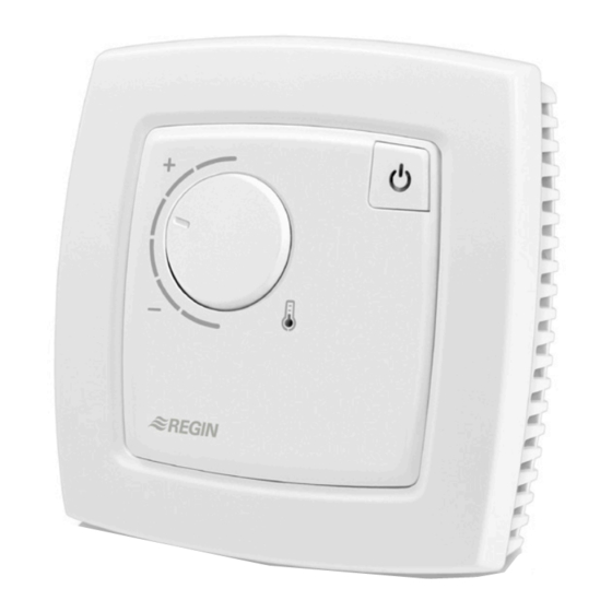
Room controller
RC-O is a room controller from the Regio Mini series, intended to
control heating and cooling in a zone control system. Installation is
directly on the wall or on an electrical connection box. The controller
does not have a communication connection.
Technical data
Supply voltage
18...30 V AC, 50...60 Hz
Internal consumption
2.5 VA
Ambient temperature
0...50°C
Ambient humidity
Max 90% RH
Storage temperature
-20...+70°C
Built-in temperature sensor NTC Type, range 0...50°C, accuracy
+/-0.5°C at 15...30°C
Inputs and outputs
Refer to connection illustrations and
table below
Connection terminals
Lift type for cable cross-section 2.1 mm
Protection class
IP20
Material, casing
Polycarbonate, PC
Weight
110 g
Dimensions
95 x 95 x 31 mm
Installation
Place the controller in a location that has a temperature representative for
the room. A suitable location is approx. 1.6 m above floor level in a place
with unobstructed air circulation.
Remove the frame by depressing the locking tab in the lower edge of the
cover with a screwdriver. See figure 1.
Then prize out the electronics cassette using the four rectangular screwdri-
ver slots and levering against the edge of the bottom plate. See figure 2.
Note: Take care not to damage the electronics when inserting the screw-
driver into the slots.
Figure 1
The bottom plate with terminals has a number of fixing hole combina-
tions. Select suitable holes (see figure 3) and screw the bottom plate onto
the wall or connection box, so that the arrows on the bottom plate point
upwards. Do not tighten the screws too hard!
With surface-mounted cabling, break-out suitable holes from the marks in
the plastic.
2
RC-O
Occupancy button
Setpoint knob
LED
°C
°C
Figure 4. Connection diagram for RC-O
Figure 2
Figure 5. Alternative connection for terminals 31, UI1, and terminal
33, DI2/CI, terminal 23, UO1, and terminal 24, UO2.
10 11 12 13 14
20 21 22 23 24
UP
UP
68
60
30 31 32 33
40 41 42 43
Figure 3. Bottom plate with mounting alternatives and location of
terminals (dimensions in mm.)
30
AI1
G
10
31
UI1
G0
11
32
DI1
DO1
12
33
DI2/CI
-
13
-
14
40
+C
GDO
20
41
AGnd
G0
21
42
-
-
22
43
-
UO1
23
UO2
24
30
AI1
G
10
31
UI1
G0
11
32
DI1
DO1
12
33
DI2/CI
-
13
-
14
40
+C
GDO
20
41
AGnd
G0
21
42
-
-
22
43
-
UO1
23
UO2
24
24 V AC
G0
G
G
G0
Y
G
G0
Y
1
Advertisement

Related Manuals for Regin REGIO RC-O


Summary of Contents for Regin REGIO RC-O
- Page 1 INSTRUCTION REGIO RC-O Occupancy button Setpoint knob 10 11 12 13 14 20 21 22 23 24 30 31 32 33 40 41 42 43 Installation Figure 3. Bottom plate with mounting alternatives and location of Place the controller in a location that has a temperature representative for terminals (dimensions in mm.)
- Page 2 This setting is used when UO1 is connected to a thermal ac- position of DIP-switch SW8. This setting refers closed window. tuator of type Regin RTAM-24 (NC). In the event of a power to which type of actuator, NC or NO it is intended cut the valve will close.
- Page 3 Occupancy detector Contact An occupancy detector is connected for local control of the operating AB Regin, Box 116, 428 22 Kållered, Sweden mode between Preset operating mode and Bypass. Tel: +46 31 720 02 00, Fax: +46 31 720 02 50 www.regin.se, info@regin.se...
-
Page 4: Installation
INSTRUKTION REGIO RC-O °C 24 V AC Läs denna instruktion innan produkten °C monteras och ansluts DI2/CI Rumsregulator AGnd RC-O är en rumsregulator i Regio Mini-serien avsedd att styra värme Figur 1 Figur 2 och kyla i efterbehandlingssystem. Montage sker direkt på vägg eller eldosa. - Page 5 33 och 41, AGnd. Denna inställning används vid anslutet termiskt ställdon typ alternativt Regin RTAM-24 (NC) på UO1. Vid ev. spänningsavbrott i systemet stänger ventilen. Fönsterkontakt (DI) Val NO i regulatorn ger omvänd verkan på utgång UO1, Potentialfri kontakt ansluts mellan plint 33 och 40, minskande utsignal (kortare pulser) för ökande utstyrning.
- Page 6 För lokal styrning av driftläget mellan Förinställt driftläge och Bypass ansluts en närvarodetektor. Kontakt AB Regin, Box 116, 428 22 Kållered Närvaroknappen Tel: +46 31 720 02 00, Fax: +46 31 720 02 50 Närvaroknappen på framsidan av regulatorn växlar mellan driftlägena www.regin.se, info@regin.se...
- Page 7 INSTRUCTION REGIO RC-O Veuillez lire cette instruction avant de procéder à l'installation et au raccordement de l'appareil. DI2/CI Régulateur d’ambiance RC-O est un régulateur d’ambiance de la gamme Regio Mini qui AGnd permet de réguler le chauffage et le refroidissement dans les systè-...
- Page 8 Sortie analogique Borne 23, UO1. type chrono-proportionnel, pour une plus grande DI2/CI Détecteur de condensation de Regin, KG-A/1 pour actionneur pour moteur de souplesse Le signal de sortie de UO1 peut être (RU). Le détecteur est branché sur les bornes 33 thermique 24 V vanne 0...10 V DC...
- Page 9 à 18 °C, elle Regin Control SARL, 32 rue Delizy, 93500 Pantin par défaut. Lorsque le bouton de présence est maintenu appuyé pendant passe en mode refroidissement.
- Page 10 ANLEITUNG REGIO RC-O Diese Anleitung vor Installation und Verdrahtung des Produktes bitte durchlesen DI2/CI Raumregler Der RC-O ist ein Raumregler aus der Regio Mini-Reihe, der für die AGnd Heiz- und Kühlregelung in einem Zonenregelsystem geeignet ist. Die Abb.1 Abb. 2 Montage erfolgt direkt an die Wand oder an eine Anschlussdose.
- Page 11 Analoge Masse, Bezug für AI und UI (mit Ana- Diese Einstellung wird für UO1 bei Anschluss eines thermi- log- und Digitalfunktion) Für 0...10 V DC-Ventilstellantrieb, max. 5 mA schen Stellantriebs der Sorte Regin RTAOM-24 (NO) verwen- (WE). Die 0…10 V-Eingangsklemme des 42-43 Keine Funktion det.
- Page 12 Die Präsenztaste auf der Reglervorderseite schaltet Kontakt zwischen dem Bypass-Modus und dem voreingestellten Betriebsmo- Regin Controls Deutschland GmbH dus hin- und her. Im Bypass-Modus wird eine Schaltuhr aktiviert, die Tel: +49 30 77 99 40, Fax: +49 30 77 99 479 nach zwei Stunden bewirkt, dass wieder in voreingestellten Betriebs- www.regincontrols.de, info@regincontrols.de...
Need help?
Do you have a question about the REGIO RC-O and is the answer not in the manual?
Questions and answers