Advertisement
Quick Links
GFK-160VF Fan Kit
This fan kit has been tested for use with specific Hearth & Home Technologies products. Check with your local build-
ing code agency before you begin installation to ensure compliance with local codes, including the need for permits and
follow-up inspections. If you encounter any problems regarding code approvals, or if you need clarification of any of the
instructions contained here, contact your Hearth & Home Technologies dealer. For the dealer nearest you, please visit www.
hearthnhome.com.
CAUTION! Risk of Cuts, Abrasions or Flying Debris.
Wear protective gloves and safety glasses during installa-
tion. Sheet metal edges are sharp.
Introduction
The GFK-160VF fan has been designed to circulate room
air through the firebox or appliance or appliance to enhance
heat output. The GFK-160VF fan system operates on 120
VAC, 60 Hz power. This is available through a receptacle in
the factory installed junction box. The junction box is locat-
ed in the controls compartment of the firebox or appliance.
A variable speed control is provided with the fan system to
provide quiet forced air flow at the desired speeds. A tem-
perature sensor switch, which automatically turns the fan
ON/OFF is also provided with this kit.
NOTE: The variable speed control and temperature
sensor switch are not used with some remote control
systems.
Kit Contents:
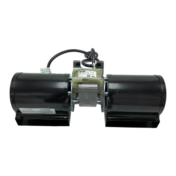
Compare system components in Figure 1 with the actual
parts received. If any parts are missing or damaged, con-
tact your dealer before starting installation. Do not install a
damaged light kit.
CAUTION! Do not install damaged components.
1.
11.
12.
Figure 1. System Contents
Hearth & Home Technologies • GFK-160VF Fan Kit Installation Instructions • 4136-920 • Rev C • 8/22
2.
3.
9.
10.
7.
8.
1. Speed Control
2. Fan
3. Air Deflector (2)
4. Power Cord
5. Screws (4)
6. Magnets (2)
SRV4137-306
SRV4137-304
SRV4137-128
SRV4121-119
SRV230-0060
Installation Precautions
The GFK-160VF Fan Kit is tested and safe when installed in
accordance with this installation manual. It is your respon-
sibility to read all instructions before starting installation and
to follow these instructions carefully during installation to as-
sure maximum benefit from, and safe operation of the fan.
This fan is carefully engineered and must be installed only
as specified. If you modify it or any of its components, you
may cause a fire hazard and will void the WARRANTY. In
addition, such action may void the coverage provided by the
owner's home insurance.
CAUTION! All wiring should be done by a qualified
electrician and shall be in compliance with local codes
and with the National Electric Code ANSI/NFPA NO.
70-current (in the United States), or with the current
CSA C22.1 Canadian Electric Code (in Canada).
Installation Instructions
4.
WARNING: Risk of Shock! Turn electrical power off
at the circuit breaker before beginning this installation.
5.
NOTE: The factory installed junction box in the fire-
6.
box or appliance must be wired with 110 VAC before
installing this kit. See firebox or appliance Installation
Instructions.
Installation
Instructions
7. Wire Clips (2)
8. Control Knob & Nut
9. Wall Box Plate
10. Instructions
11. Wire Harness
12. Temperature Sensor
13. Foam Tape (2) Not
Service Parts
Part Number
100-510A
Shown
Description
Power Cord
Wire Harness
Air Deflector
Wall Box Plate
Speed Control
Temperature Sensor
1
Advertisement

Related Manuals for Hearth and Home Technologies GFK-160VF


Summary of Contents for Hearth and Home Technologies GFK-160VF
- Page 1 110 VAC before installing this kit. See firebox or appliance Installation Instructions. Figure 1. System Contents Hearth & Home Technologies • GFK-160VF Fan Kit Installation Instructions • 4136-920 • Rev C • 8/22...
- Page 2 See Figure 4. 4. Pull Burner Assembly forward slightly and lift, removing it from the appliance, set aside. See Figure 7. Figure 7 Figure 4 Hearth & Home Technologies • GFK-160VF Fan Kit Installation Instructions • 4136-920 • Rev C • 8/22...
- Page 3 Set cover aside. See Figure 10. 4. Secure Temperature Sensor using (2) screws provided. See Figure 13. Figure 10 Figure 13 Hearth & Home Technologies • GFK-160VF Fan Kit Installation Instructions • 4136-920 • Rev C • 8/22...
- Page 4 (if applicable). Figure 16. See Figure 19 and 20. 2. Install Control Nut and Control Knob. Figure 16 Figure 19 - (BUF/ACUF/IDOL) Hearth & Home Technologies • GFK-160VF Fan Kit Installation Instructions • 4136-920 • Rev C • 8/22...
- Page 5 2. Turn the 110-120 VAC service “ON” at the circuit break- 1. Position Fan between firebox and outer wrap, through rear access as shown in Figure 22. Figure 22 - (LCUF) Hearth & Home Technologies • GFK-160VF Fan Kit Installation Instructions • 4136-920 • Rev C • 8/22...
-
Page 6: Maintenance
FAN CONTROL MOUNTED IN FIREBOX MOUNTED IN FIREBOX JUNCTION BOX Figure 24 - Standard Wiring Diagram - (BUF/ACUF/LCUF AND IDOL Standing Pilot models) Hearth & Home Technologies • GFK-160VF Fan Kit Installation Instructions • 4136-920 • Rev C • 8/22... - Page 7 KNOCKOUT LIGHT CONTROL MOUNTED IN FIREBOX JUNCTION BOX Figure 25 - Wiring Diagram - Remote Fan Control (BUF/ACUF/LCUF and IDOL Standing Pilot models) Hearth & Home Technologies • GFK-160VF Fan Kit Installation Instructions • 4136-920 • Rev C • 8/22...
- Page 8 KNOCKOUT FAN CONTROL MOUNTED IN FIREBOX JUNCTION BOX Figure 26 - Wiring Diagram - Remote Light Control (BUF/ACUF/LCUF and IDOL Standing Pilot models) Hearth & Home Technologies • GFK-160VF Fan Kit Installation Instructions • 4136-920 • Rev C • 8/22...
- Page 9 POWER CORD WIRE HARNESS KNOCKOUT JUNCTION BOX Figure 27 Wiring Diagram - Remote Fan and Light Controls (BUF/ACUF/LCUF and IDOL Standing Pilot models) Hearth & Home Technologies • GFK-160VF Fan Kit Installation Instructions • 4136-920 • Rev C • 8/22...
-
Page 10: Power Cord
Please contact your Hearth & Home Technologies dealer with any questions or concerns. For the location of your nearest Hearth & Home Technologies dealer, please visit www.hearthnhome.com. Hearth & Home Technologies • GFK-160VF Fan Kit Installation Instructions • 4136-920 • Rev C • 8/22...
Need help?
Do you have a question about the GFK-160VF and is the answer not in the manual?
Questions and answers