Advertisement
Models:
Cinch Pipe & Termination Cap System
These instructions are replacing VP (for Heatilator) and DV (for Heat-N-Glo) pipe assembly
instructions. See the appliance installation instructions for confi guration of vent assembly
and clearances to pipe.
If you need assistance during installation, contact your local dealer or the Technical Serices Dept., Hearth & Home Technologies
Inc., phone 1-800-927-6841 or 1-888-427-3973.
If DVP-AD adapters are used off the top of the appliance, the termination height will be raised by 2-3/4 in. overall
height.
Hearth & Home Technologies Inc. • Cinch Pipe & Term Caps • 4033-900 Rev K • 05/05
Sharp Edges
•
Wear protective gloves and safety glasses
during installation.
Hearth & Home Technologies disclaims any
responsibility for, and the warranty will be
voided by, the following actions:
•
Installation and use of any damaged vent
system component.
•
Modifi catoin of the vent system.
•
Installation other than as instructed by
Hearth & Home Technologies.
•
Installation and/or use of any component
part not approved by Hearth & Home
Technologies.
Any such action may cause a fi re hazard.
Do not mix pipe, fittings or joining
methods from different manufacturers.
Note: An arrow ( ) found in the text signifi es change in content.
CAUTION
WARNING
WARNING
Installation
Instructions
1
Advertisement
Table of Contents

Subscribe to Our Youtube Channel
Related Manuals for Hearth and Home Technologies Cinch Pipe & Termination Cap System


Summary of Contents for Hearth and Home Technologies Cinch Pipe & Termination Cap System
- Page 1 Models: Cinch Pipe & Termination Cap System These instructions are replacing VP (for Heatilator) and DV (for Heat-N-Glo) pipe assembly instructions. See the appliance installation instructions for confi guration of vent assembly and clearances to pipe. If you need assistance during installation, contact your local dealer or the Technical Serices Dept., Hearth & Home Technologies Inc., phone 1-800-927-6841 or 1-888-427-3973.
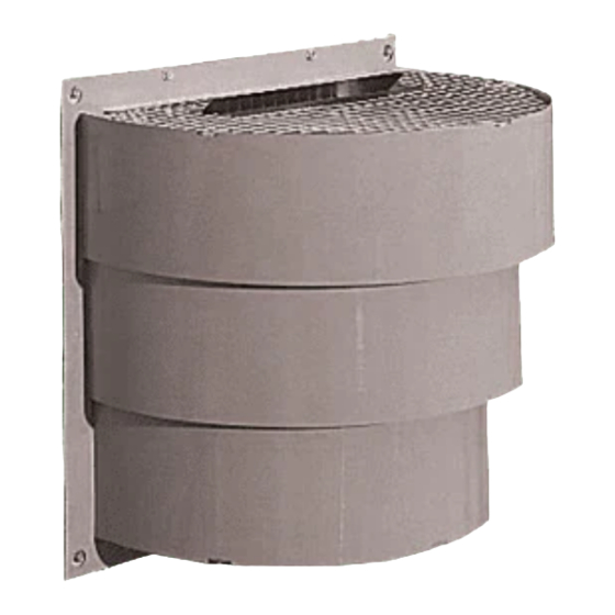
- Page 2 Parts and Descriptions (not shown) Hearth & Home Technologies Inc. • Cinch Pipe & Term Caps • 4033-900 Rev K • 05/05 DVP-TV Vertical termination cap. Includes storm collar and fastener pack. DVP-TB1 Basement/window well termination cap. Includes fas- tener pack. DVP-TRAP1 Horizontal termination cap with 1-3/4 in.
- Page 3 DVP-TRAPFL Flashing DVP-TRAP1 DVP-TRAP2 Termination Cap Components Description DRC-RADIUS Cap Shield COOL-ADDM Cap Shield - pack of six DVP-TV Vertical Termination Cap DVP45 45° Elbow DVP90ST 90° Elbow RF6M Roof Flashing (vertical termination for 0/12 to 6/12 pitch) - pack of four RF12M Steep Pitch Roof Flashing (for 7/12 to 12/12 pitch) - pack of six DVP4...
- Page 4 Vent depth is measured from the back of the appliance to the outer edge of the exterior wall. See Table 1 and Figure 1. DVP-TRAPK1 Top Vent Appliance Novus 4-1/2 in. to 6-1/4 in. 4-1/8 in. to 5-7/8 in. Caliber 4-1/8 in.
-
Page 5: Installing Vent Pipe
Installing Vent Pipe Note: For termination cap installations only, go directly to Sec- tion E. A. Clearances for the Vent Sections • Top Vented Direct Vent Appliances For all top vented, direct vent appliances, clearances to combustible materials from the venting system need to be maintained as shown in Figure 2.1. -
Page 6: Assemble Vent Sections
C. Assemble Vent Sections WARNING Fire Risk Exhaust Fumes Risk • Overlap pipe slip sections at least 1-1/2 inches. • Use pilot holes for screws. • Screws must not exceed one inch long. • Pipe may separate if not properly joined. - Page 7 Assemble Minimum Installation (MI) Sections MI sections are non-unitized so that they can be cut to a specifi c length. Cut these sections to length from the non- expanded end (see Figure 2.9). They can then be attached by fi rst connecting the expanded end of the MI inner fl...
-
Page 8: Disassemble Vent Sections
Secure the Vent Sections Vertical sections of pipe must be supported every 8 ft after the 25 ft maximum unsupported rise. The vent support or plumber’s strap (spaced 120° apart) may be used to do this (see Figures 2.12 and 2.13). Horizontal sections of vent must be supported every 5 ft with a vent support or plumber’s strap. -
Page 9: Install The Heat Shield And Horizontal Termination Cap
E. Install the Heat Shield and Horizontal Termination Cap WARNING A 1-1/2 in. minimum overlap MUST be maintained on the telescoping fl ue section of the cap. WARNING Fire Risk Exhaust Fumes Risk Impaired performance of appliance. • Overlap pipe slip sections at least 2 in. •... -
Page 10: Vertical Penetration Framing
F. Vertical Penetration Framing WARNING Fire Risk Keep loose materials or blown insulation from touching the vent pipe. • National building codes recommend using attic shield to keep loose materials/blown insulation from contacting vent. • Hearth & Home Technologies requires the use of an attic shield. -
Page 11: Install Roof Flashing And Vertical Termination Cap
G. Install Roof Flashing and Vertical Termination Cap To install roof fl ashing see Figure 2.19. For installation of vertical termination cap see minimum vent heights for various pitched roofs (Figure 2.19) . 20 in. 24 in. min. (508 mm) (610 mm) Lowest Discharge... -
Page 12: Assemble And Install Storm Collar
H. Assemble and Install Storm Collar CAUTION Sharp Edges! • Wear protective gloves and safety glasses during installation. Connect both halves of the storm collar with two screws (see Figure 2.21). Wrap the storm collar around the exposed pipe section and align brackets.
Need help?
Do you have a question about the Cinch Pipe & Termination Cap System and is the answer not in the manual?
Questions and answers