Table of Contents
Advertisement
Quick Links
Quick Installation Guide
Industrial 5-port Unmanaged
Ethernet Switch
DS105
www.womaster.eu
・Overview
DS105 is a cost effective industrial 5-port Ethernet switch for industrial
Ethernet connection. The rugged design can stand for harsh
environment and wide temperature (from -40 to 75°C) use. Ultra low
power design consumes less than 1W during full traffic. The compact
size can fit in for space limited installation such as vehicle wall-
mounting or Din-mount for cabinets. Micro USB DC 5V power input is
flexible for installation.
・Package Checklist
✓ 1 x Product Unit
✓
1 x 3-pin Removable Terminal Connector
✓
1 x DIN Bracket set
✓
1 x Quick Installation Guide
Optional Accessory (for detailed information please refer to the
Datasheet)
・Installation
Wall mount
Two wall mounting plates are installed at the left and right side of the
switch. Use the two hook holes at the corners of each wall mounting
plate or the middle hole to hang the switch on the wall them then
screw tightly.
Wall Mount Clip
DIN Rail mount
Attach the DIN Rail Clip to the two wall mount plates. The DIN Rail
should comply with DIN EN50022 standard. Using wrong DIN rail may
cause unsafe installation.
Power Input (Terminal Block or Micro USB)
Terminal Block
1) Insert the positive and negative wires into the V+, V- and G contact
on the terminal block connector.
2) Tighten the wire-clamp screws.
3) Connect the power wires to suitable DC Switching type power
supply.
V+
USB POWER INPUT
5 VDC
** Caution: Do not connect the power supply before and after
wiring to avoid damage or electric shock.
** Note: It is supported with Redundant power design:
5~30V/USB 5V
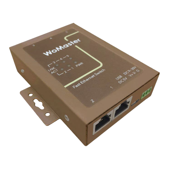
・Appearance
DS105
System LED
・1 x Power
・5 x Ethernet Port
Wall Mount Clip
Ethernet Network
・5-port 10/100MBase-TX
USB 5V Power Input
・Micro USB connector
(3-port on top, 2-port on bottom)
Top Panel
Bottom Panel
・LED Indicator
V-
G
DC 5 ~ 30V
LED
PWR
Ethernet Port
(Port 1~5)
Wall Mount Clip
・Safety Precautions
➢ Turn off DC power input source before connecting the DC Power
supply module to the terminal block connectors. Do not turn-on the
source of DC power module and make sure all connections were well
Integrated Power
established, then power on the DC source to powering the Switch
Connector
・ 3-Pin Removable
device.
Terminal Connector
➢ Never install or work on/with the equipment or the cabling during the
period of lightning activity.
Power
1
2
Connector
Micro USB
Power Input
3
4
5
3
4
5
LNK
ACT
2
1
PWR
Status
Description
Green On
DC-IN Power is On
Off
No Power in DC-IN
Green On
Links established
Green Blinking
Packets transmitting/receiving
Off
Link is inactive
Advertisement
Table of Contents

Related Manuals for WoMaster DS105


Summary of Contents for WoMaster DS105
- Page 1 ・Overview USB POWER INPUT 5 VDC DS105 is a cost effective industrial 5-port Ethernet switch for industrial Ethernet connection. The rugged design can stand for harsh environment and wide temperature (from -40 to 75°C) use. Ultra low power design consumes less than 1W during full traffic. The compact...
- Page 2 ・Disclaimer WoMaster reserves the right to make changes to this QIG or to the product hardware at any time without notice. It is the user’s responsibility to determine whether there have been any such updates or amendments herein.
Need help?
Do you have a question about the DS105 and is the answer not in the manual?
Questions and answers