Advertisement
Quick Links
Quick Installation Guide
Industrial DIN Rail PoE Switch
DP310
Industrial DIN Rail Ethernet Switch
DS310
www.womaster.eu
・Overview
DP310 and DS310 are industrial 10-port L2 Managed PoE switches
equipped with 8-port Fast Ethernet, both switches provide additional 2-
port RJ45/SFP combo Gigabit Ethernet uplink, prioritized stream such as
video and VoIP are also optimized. High speed uplink connection to
higher level backbone switches with Ring network redundancy technology
ensures the reliability of high-quality video transfer. For the best traffic
control, management side features LACP, VLAN, QinQ, IGMP snooping,
QoS, etc. DP310 is an IEEE 802.3af/at compliant PoE switch for enabling
devices when power sources are not available. All of the 8 ports can
deliver up to 30W power per port to the high-power requiring devices.
DP310
10/100Base-TX
8
100/1000Base-T
2, Combo
PoE Standard
IEEE 802.3af/at
46~57VDC
(50~57VDC for
Power input
802.3at)
・Package Checklist
1 x Product Unit (Without SFP transceiver)
•
•
1 x 8-pin Removable Terminal Connector
•
1 x Din Clip
•
1 x Quick Installation Guide
Optional Accessory (for detailed information please refer to the
Datasheet):
100Mbps SFP Transceiver
•
•
1000Mbps SFP Transceiver
•
RS232 Console Cable
・Installation
DIN Rail mount
To mount the switch on the DIN
Rail track, insert the upper end
of the DIN‐Rail clip into the
back of the DIN‐Rail track from
its upper side and lightly push
the bottom of the DIN‐Rail clip
into the track. The DIN Rail
should comply with DIN
EN50022 standard. Using
wrong DIN rail may cause
unsafe installation.
Grounding Screw
For avoiding system damage by
noise or electric shock, establish a
direct connection between the
ground screw and the grounding
surface prior to connecting devices.
Wiring the Relay Output
The relay output of the 2-pin
terminal block connector are used
to detect user-configured events.
The two wires attached to the fault
contacts form a close circuit when a
user-configured event is triggered.
If a user-configured event does not
occur, the fault circuit remains
opened.
DS310
8
Wiring the Power Input
1) Insert the positive and negative
2, Combo
wires into the V+ and V- contact on
the terminal block connector.
-
2) Tighten screws when the
wire is connected.
3) Connect the power
18~60VDC
wires to suitable DC Switching type
power supply.
Wiring the Digital Input
To wire the DI on the Terminal
block, loosen screws by screw
driver on the terminal block
connector, insert the positive and
negative wires into the V+ and V-
contact and then tighten screws
after the DI wire is connected.
USB Port
Use the USB port in order to save
or restore the configuration and
upload the firmware upgrade file.
For further configurations, please
refer to User Manual.
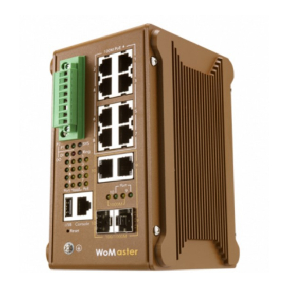
・Appearance
Grounding Screw
Advertisement

Related Manuals for WoMaster DP310


Summary of Contents for WoMaster DP310
- Page 1 LACP, VLAN, QinQ, IGMP snooping, contacts form a close circuit when a QoS, etc. DP310 is an IEEE 802.3af/at compliant PoE switch for enabling user-configured event is triggered. devices when power sources are not available. All of the 8 ports can If a user-configured event does not deliver up to 30W power per port to the high-power requiring devices.
- Page 2 Start -> Program -> Accessories -> Communication -> Hyper Terminal. PoE LED PoE is enabled but no PD is WoMaster reserves the right to make changes to this QIG or to the Amber Blinking • Give a name to a new console connection.
Need help?
Do you have a question about the DP310 and is the answer not in the manual?
Questions and answers