Table of Contents
Advertisement
Quick Links
Quick Installation Guide
Industrial 14G L3 Managed M12
PoE Switch
MP614 Series
www.womaster.eu
www.womaster.eu
・ Overview
The new exclusive MP614 Series is the first full Gigabit routing PoE switch
designed for Layer 3 network on rail public transport. Equipped with 14
rugged Gigabit M12 ports, 8 of which supply intelligent PoE/PoE+ and 2
of which with embedded link bypass function guarantees sustainable
connectivity in critical applications, even in case of device/power fault.
The advanced Layer 3 routing protocols such as IP/VLAN routing, RIP,
OSPF, VRRP are fully compatible with your backbone network. Full 14
Gigabit ports bring forward an ultra speed connectivity without any
bottleneck. The comprehensive Cyber Security design safeguards the
network from outside intrusion.
Model Name
Description
Industrial 14G L3 Managed M12 A-code
MP614-HV-A
PoE Switch, 110V
Industrial 14G L3 Managed M12 X-code
MP614-HV-X
PoE Switch, 110V
Industrial 14G L3 Managed M12 A-code
MP614-MV-A
PoE Switch, 54V
Industrial 14G L3 Managed M12 X-code
MP614-MV-X
PoE Switch, 54V
Industrial 14G L3 Managed M12 A-code
MP614-WV-A
PoE Switch, 24-110V
Industrial 14G L3 Managed M12 X-code
MP614-WV-X
PoE Switch, 24-110V
・ Package Checklist
.1 x Product Unit
.1 x Wall Mount Kit (2 x Wall mount plate)
.1 x Quick Installation Guide
Optional Accessory for detailed information please refer to the Datasheet
.M12 A-code 4Gb USB disk for device configuration, firmware update
.Console Cable DB9 Male to M12-A-code Male, 1Meter
.Field assembled M12 connector, 4-pin, A-code
・ Installation
Wall mounting
Follow the steps to install the wall-mounting plate:
1. Install the wall-mounting plate onto the side panel of the switch.
2. Tightened all of the screws well.
3. Use the hook holes at the corners of the wall mounting plate to hang the
switch on the wall.
Wall Mounting Screw
on front side
Grounding
There are two grounding screws on the device.
One is located on the front side of the switch
and the other one is located on the left side. For
avoiding system damage by noise or electric
shock, establish a direct connection between
the device and earth ground. Please refer to
Appearance Section.
MP614 Series Connector
MP614 Series Switch uses several types of M12 connector for the
power input, Gigabit ports and console port for management and
system backup. The connector is different from the common connector
in other switches. Below are some descriptions about the connector.
100/1000Base-T, M12 8 pin A/X-Code Female
100/1000Base-T
Pin
MP614-HV/MV/WV-A MP614-HV/MV/WV-X
1
D3-
2
D4+
3
D4-
4
D1-/PoE V+
5
D2+/PoE V-
6
D1+/PoE V+
7
D3+
8
D2-/PoE V-
Wiring the Power Inputs
For DC power inputs (MP614-HV: 110VDC (77~137.5VDC) / MP614-MV:
54VDC (46~57VDC) / MP614-WV: 24/48/110VDC (16.8~137.5VDC))
1. Insert positive and negative wires into V+ and V- contacts respectively
of the M12 connector (Plug-side).
2. Tighten the nuts to prevent the loosening of the M12 connectors.
3. Power input supports power redundancy and polarity-reverse protec-
tion functions.
*The Power Supply is not included, please prepare one yourself.
Power Connector
Console/ USB Port – M12 8 pin A-Code Female
Power Connector
Wall Mounting Screw
on back side
Grounding Screw
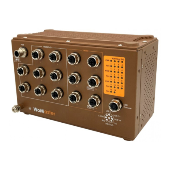
・ Appearance
IEEE 802.3 af/at PoE
・ 8-port 100/1000MBase-T M12
8-pin A-Code or X-Code
Power Connector
・ 1 x M12 4 pin A-Code
D1+/PoE V+
D1-/PoE V+
D2+/PoE V-
D2-/PoE V-
D4+
D4-
Gigabit Ethernet
D3-
・ 6-port 100/1000MBase-T M12
Ground Screw
8-pin A-Code or X-Code
D3+
・ 2-port with Bypass Function
(Port 13/14)
Pin
Description
1
V+
2
V+
3
V-
4
V-
Pin
Description
1
TX
2
RX
3
Signal Ground
4
N/A
5
USB Data+
6
USB Data-
7
USB Power 5V
8
USB GND
System LED
・ 1 x Power
・ 1 x System Status
・ 1 x Ring Status
・ 1 x ALM
・ 14 x Ethernet Port
・ 8 x PoE
Wall Mount
Screw Holes
for Front / Back
Panel
Easy System Management
・ 1 x M12 8 pin A-Code
・ USB for Configuration/Firmware update
・ RS232 console
Advertisement
Table of Contents

Related Manuals for WoMaster MP614 Series


Summary of Contents for WoMaster MP614 Series
- Page 1 USB Data- avoiding system damage by noise or electric shock, establish a direct connection between The new exclusive MP614 Series is the first full Gigabit routing PoE switch USB Power 5V the device and earth ground. Please refer to designed for Layer 3 network on rail public transport. Equipped with 14...
- Page 2 Green Blinking Firmware Updating System LED WoMaster reserves the right to make changes to this QIG or to the ・ Type http://IP_address in your browser (the default IP address is product hardware at any time without notice. It is the user’s responsibility http://192.168.10.1/)
Need help?
Do you have a question about the MP614 Series and is the answer not in the manual?
Questions and answers