
Related Manuals for WoMaster DP612


Summary of Contents for WoMaster DP612
-
Page 1: Cover
COVER DP612 Industrial 12G Layer 3 Managed PoE Switch DS612 Industrial 12G Layer 3 Managed Switch Jan.08.2018 V.1... - Page 2 Disclaimer WoMaster reserves the right to make changes to this Manual or to the product hardware at any time without notice. Information provided here is intended to be accurate and reliable. However, it might not cover all details and variations in the equipment and does not claim to provide for every possible contingency met in the process of installation, operation, or maintenance.
-
Page 3: Table Of Contents
TABLE OF CONTENTS COVER......................................... 1 TABLE OF CONTENTS ..................................3 INTRODUCTION ..................................6 1.1 OVERVIEW ............................... 6 1.2 MAJOR FEATURES ............................. 7 2. HARDWARE INSTALLATION ................................ 8 HARDWARE DIMENSION ........................8 WIRING THE POWER INPUTS ......................10 WIRING THE ALARM RELAY OUTPUT (DO) ..................11 WIRING THE DIGITAL INPUT (DI) ...................... - Page 4 3.3.1 PoE STATUS ............................43 3.3.2 PoE CONTROL ............................44 3.3.3 PoE SCHEDULING ..........................46 3.3.4 ALIVE CHECK ............................46 3.3.5 PoE EVENT............................. 47 3.4 REDUNDANCY ............................48 3.4.1 RSTP SETTINGS ............................48 3.4.2 MSTP SETTINGS ............................. 52 3.4.3 ERPS SETTINGS ............................55 3.4.3.1 ERPS SETTINGS ..................................
- Page 5 3.10.2 IEEE 802.1X ............................97 3.11 WARNING ............................101 3.11.1 RELAY OUTPUT ..........................101 3.11.2 EVENT TYPE ............................102 3.11.3 SYSLOG SETTING ..........................103 3.11.4 EMAIL ALERT ............................. 104 3.12 DIAGNOSTICS ............................. 105 3.12.1 LLDP SETTING ............................ 105 3.12.2 MAC TABLE ............................106 3.12.3 PORT STATISTICS ..........................
-
Page 6: Introduction
LACP, VLAN, QinQ, QoS, IGMP snooping, and etc. In order to uplink connection, the DP612/DS612 provides 4 SFP ports that can prioritize stream, such as video and also optimize VoIP. 100/1000Mbps SFP type fiber transceiver and DDM (Digital Diagnostic Monitoring) type SFP transceivers also equipped the switch for diagnosing transmission problem through maintenance and debugging of the signal quality. -
Page 7: Major Features
Below are the major features of DP612/DS612 Switch: 12-port Full Gigabit Ethernet with 8-port RJ-45 and 4-port SFP IEEE 802.3af 15.4W / IEEE 802.3at 30W High Power PoE (DP612) 240W ultra high PoE budget and excellent power efficiency even in 75... -
Page 8: Hardware Installation
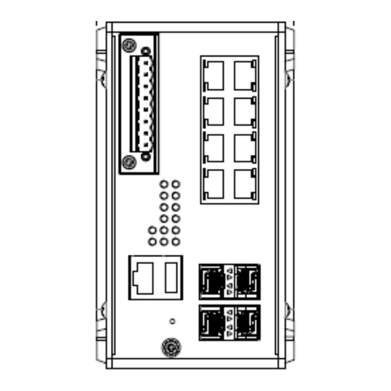
This chapter introduces hardware, and contains information on installation and configuration procedures. 2.1 HARDWARE DIMENSION Dimensions of DP612: 85.5 x 150 x 126.5 (W x H x D) / without DIN Rail Clip Dimensions of DS612: 85.5 x 150 x 126.5 (W x H x D) / without DIN Rail Clip... - Page 9 Front Panel Layout The front panel from DP612 and DS612 switches includes 8 ports Giga Ethernet, 4 SFP ports, System LED, USB for configuration/firmware management, RJ-45 diagnostic console, 1 x 8-pin terminal block connector (4 pin for power inputs, 2 pin for digital input and 2 pin for alarm relay output) and 1 chassis grounding screw. The difference is for DP612 it is provided with PoE LED.
-
Page 10: Wiring The Power Inputs
2.2 WIRING THE POWER INPUTS Power Input port in the switch provides 2 sets of power input connections (P1 and P2) on the terminal block. x On the picture below is the power connector. Wiring the Power Input 1. Insert the positive and negative wires into the V+ and V- contact on the terminal block connector. 2. -
Page 11: Wiring The Alarm Relay Output (Do)
2.3 WIRING THE ALARM RELAY OUTPUT (DO) The relay output contacts are located on the front panel of the switch. The relay output consists of the 2-pin terminal block connector that used to detect user-configured events. The two wires attached to the fault contacts form a close circuit when a user-configured event is triggered. -
Page 12: Wiring The Digital Input (Di)
2.4 WIRING THE DIGITAL INPUT (DI) The Digital Input accepts one external DC type signal input that consists of two contacts on the terminal block connector on the switch’s top panel. And can be configured to send alert message through Ethernet when the signal is changed. -
Page 13: Connecting The Grouding Screw
2.5 CONNECTING THE GROUDING SCREW Grounding screw is located on the front side of the switch. Grounding Screw helps limit the effects of noise due to electromagnetic interference (EMI) such as lighting or surge protection. Run the ground connection from the ground screw to the grounding surface prior to connecting devices. -
Page 14: Web Management Configuration
3. WEB MANAGEMENT CONFIGURATION To access the management interface, WoMaster has several ways access mode through a network; they are web management, console management and telnet management. Web interface management is the most common way and the easiest way to manage a network, through web interface management, a switch interface offering status information and a subset of switch commands through a standard web browser. - Page 15 In this Web management for Featured Configuration, user will see all of WoMaster Switch’s various configuration menus at the left side from the interface. Through this web management interface user can configure, monitoring, and set the administration functions. The whole information used web management interface to introduce the featured functions.
-
Page 16: System
3.1 SYSTEM When the user login to the switch, user will see the system section appear. This section provides all the basic setting and information or common setting from the switch that can be configured by the administrator. Following topics is included: 2.1.1 Information 2.1.2 User Account 2.1.3 IP Setting... -
Page 17: User Account
After finish the configuration, click on Submit to apply User settings. 3.1.2 USER ACCOUNT WoMaster’ switch supports the management accounts; with the Name default setting is admin and the authority allow user to configure all of configuration parameters. Below is the User Account section that consists of two interfaces, Local User and Radius Interface. -
Page 18: Radius Server
3.1.2.2 RADIUS SERVER The Remote Authentication Dial In User Service (RADIUS) mechanism is a centralized “AAA” (Authentication, Authorization and Accounting) system for connecting to network services. The fundamental purpose of RADIUS is to provide an efficient and secure mechanism for user account management. RADIUS server system allows you to access the switch through secure networks against unauthorized access. -
Page 19: Ip Setting
3.1.3 IP SETTING IP Setting section allows users to configure both IPv4 and IPv6 values for management access over the network. WoMaster switch supports both IPv4 and IPv6, and can be managed through either of these address types. 3.1.3.1 IPv4 DHCP Client When DHCP Client function is enabled, an IP address will be assigned to the switch from the network’s DHCP server. -
Page 20: Ipv6
enabled, no needs to assign the subnet mask. Default Gateway Assign the gateway for the switch here. DNS Server 1, DNS Specifies the IP address of the DNS server 1 and 2 that used in user network. Server 2 3.1.3.2 IPv6 IPv6 Setting An Ipv6 address is represented as eight groups of four hexadecimal digits, each group representing 16 bits (two octets).The groups are separated by colons (the length of Ipv6 address is 128bits. - Page 21 Neighbor Cache The IPv6 neighbor table includes the neighboring node’s IPv6 address, Interface, MAC Address, and the current state of the entry. The description of the columns is as below: TERMS DESCRIPTION Neighbor Cache The system will update Neighbor Cache automatically, and user also can click Reload to refresh the table.
-
Page 22: Date And Time
3.1.4.1 DATE AND TIME SETTING The WoMaster’ switch has a time calibration function based on information from an NTP server or user specified time and date, allowing functions such as automatic warning emails to include a time and date stamp. - Page 23 IEEE 1588 PTP IEEE 1588 IEEE 1588 was published in 2002, expands the performance capabilities of Ethernet networks to control systems that operate over a communication network. In recent years an increasing number of electrical power systems have been using a more distributed architecture with network technologies that have less stringent timing specifications. IEEE 1588 generates a master-slave relationship between the clocks, and enforces the specific timing requirements in such power systems.
-
Page 24: Ptp Setting
3.1.4.2 PTP SETTING The PTP can be set in this PTP Setting webpage in which the user can configure PTP. The top part of this figure allows the users to enable or disable the PTP function. To enable PTP on the managed switch, please choose Enable. Note that the PTP functions will not active if the Operation is disabled. -
Page 25: Dhcp Server
DHCP Server Setting WoMaster’ switch has DHCP Server Function that will provide a new IP address to DHCP Client. After enable DHCP Server function, set up the Network IP address for the DHCP server IP address, Subnet Mask, Default Gateway... - Page 26 The description of the columns is as below: TERMS DESCRIPTION Global Setting Select to Enable or Disable to activate and deactivate DHCP Server function. Address Pool Add Add address pool to local DHCP Server Address Pool List Choose the address pool setting that has been entered Network Enter the starting IP addresses for the DHCP server’s IP assignment.
- Page 27 Static Port/IP Binding List The figure below is the web interface for Static Port/IP Binding List Type the specific Port and IP address, and then click Add to add a new Port & IP address binding rule for a specific client.
- Page 28 Option 82/IP Binding List The figure below is the web interface for Option 82/IP Binding List Type the specific Circuit ID, Remote ID and IP address, and then click Add to add a new binding rule for a specific client. The description of the columns is as below: TERMS DESCRIPTION...
- Page 29 DHCP Option 82 The DHCP Relay Agent (or DHCP Option 82) makes it possible for DHCP broadcast messages to be sent over routers. The DHCP Relay Agent enables DHCP clients to obtain IP addresses from a DHCP server on a remote subnet, or those that are not located on the local subnet.
- Page 30 Relay Policy Replace - Replaces the existing option 82 field and adds new option 82 field. (This is the default setting). Keep - Keeps the original option 82 field and forwards to server. Drop - Drops the option 82 field and do not add any option 82 field. Circuit ID &...
- Page 31 2. The MAC address of the relay agent. 3. A combination of IP address and MAC address of the relay agent. 4. A user-defined string. DHCP Leased Entries The figure below shows the DHCP Leased Entries. It will show the MAC and IP address that was assigned by switch. Click the Reload button to refresh the list.
-
Page 32: Ethernet Port
3.2 ETHERNET PORT Ethernet Port section is used to access the port configuration and rate limit control. It also allows User to view port status and port trunk information. 3.2.1 PORT SETTING Port Settings section allows users to enable or disable each port function; state the speed/duplex of each port; and enable or disable the flow control of the port. -
Page 33: Port Status
Port Status provides current port status. SFP DDM WoMaster’ Industrial Switch supports the SFP module with digital diagnostics monitoring (DDM) function. User can check the physical or operational status of an SFP module via SFP DDM section. This section shows and configures the operational status, such as Scan/Eject the SFP, Enable/Disable SFP DDM, Temperature degree, Tx Power statistics, Rx Power Statistics in real time. -
Page 34: Port Trunk
Ethernet port. The member ports of the same trunk group can balance the loading and backup for each other. WoMaster’ industrial managed switches support 2 types of Port Trunk. One is LACP (dynamic) and the other is Static. Link Aggregation Control Protocol (LACP), which is a protocol running on layer 2, provides a standardized means in accordance with IEEE 802.3ad to bundle several... - Page 35 • 802.1Q VLAN will be reset. • Multicast Filtering will be reset. • Port Lock will be reset and disabled. • Set Device IP will be reset. • Mirror will be reset. After port trunk has been activated, User can configure these items again for each trunk port. Port Trunk Setting The switch can support up to 8 trunk groups with 2 trunk members.
- Page 36 Load Balance Setting Load Balance Type: Each Trunk Group can support several Load Balance types that can be seen from the table below: Type Description src-mac load distribution is based on the source MAC address dst-mac load distribution is based on the destination-MAC address src-dst-mac load distribution is based on the source and destination MAC address...
- Page 37 The description of the columns is as below: TERMS DESCRIPTION Group ID Display Trunk 1 to Trunk 5 setup in Aggregation Setting. Type Static or LACP setup in Aggregation Setting. Aggregated Ports When LACP links well, User can see the member ports in aggregated column.
-
Page 38: Rate Control
3.2.4 RATE CONTROL Rate control is a form of flow control used to enforce a strict bandwidth limit at a port. User can program separate transmit (Egress Rule) and receive (Ingress Rule) rate limits at each port, and even apply the limit to certain packet types. -
Page 39: Storm Control
3.2.5 STORM CONTROL A LAN storm appears when packets flood the LAN, creating excessive traffic and degrading network performance. Errors in the implementation, mistakes in network configuration, or users issuing a denial-of-service attack can cause a storm. Storm control prevents traffic on a LAN from being disrupted by a broadcast, DLF, or multicast storm on a port. -
Page 40: Jumbo Frame
These messages are unidirectional and do not solicit a response. Each MEP transmits a periodic multicast Continuity Check Message inward towards the other MEPs. DP612/DS612 support Hardware CCM transition. The transition/receiving interval can up to 3.3ms to support detection Gigabit Ethernet cooper interface in 10ms. - Page 41 TERMS DESCRIPTION MD Level Select the MD Level from 0~7 The eight levels range from 0 to 7. A hierarchical relationship exists between domains based on levels. The larger the domain, the higher the level value. Recommended values of levels are as follows: Customer Domain: Largest (e.g., 7) Provider Domain: In between (e.g., 3) Operator Domain: Smallest (e.g., 1)
- Page 42 TERMS DESCRIPTION Domain Association Name Choose the Domain Association Name that has been added Endpoint Type Default: Local Endpoint Choose between Local Endpoint and Remote Endpoint Local Endpoint: Set the port as the Continuity Check Message (CCM) sender. Remote Endpoint: Set the port as the Continuity Check Message (CCM) receiver.
-
Page 43: Power Over Ethernet (Poe Models Only)
WoMaster’ industrial DIN Rail PoE Switch compliant with IEEE 802.3af and IEEE 802.3at. All of WoMaster’ switches adapt 8-Port PoE injectors in port 1 to port 8, each port with the ability to deliver 30W to compatible IEEE 802.3at standard and provides 240W power budget for hall system. -
Page 44: Poe Control
The description of the columns is as below: TERMS DESCRIPTION Mode Enable/Disable/Schedule Indicates the PoE port status Status Default: Off PoE status is included Off, Powering, and Searching. Off – PoE is inactive. Powering – PoE is enabled and powering the PD. Searching –... - Page 45 PoE Port Control The description of the columns is as below: TERMS DESCRIPTION Mode Enable/Disable/Schedule port’s PoE function. Powering Mode 802.3af, 802.3at (LLDP), 802.3at (2-event) and forced mode. *Forced mode will ignore the classification behaviors and apply power onto the RJ-45, uses the forced mode must be carefully.
-
Page 46: Poe Scheduling
PD Alive Check WoMaster’ Switches support a useful function that help user to maintain the PD’s status and help use to saving the maintenance time and money. Once user defined this function, the PoE Switch will request PD system and turn-off PoE power if PD system does not echo the request. -
Page 47: Poe Event
The description of the columns is as below: TERMS DESCRIPTION IP address PD’s IP-address that installed on the port. Cycle time User measured the PD system boots duration time. *Most of PD system – IP camera will take at least 40~50 seconds. Here, we suggest that user sets the cycle time to 90 seconds. -
Page 48: Redundancy
3.4 REDUNDANCY Redundancy role on the network is to help protect critical links against failure, protects against network loops, and keeps network downtime at a minimum. Sustainable, uninterrupted data communication network is critical for industrial applications. Network Redundancy allows user to set up redundant loops in the network to provide a backup data transmission route in the event that a cable is inadvertently disconnected or damaged. - Page 49 networks. A spanning tree algorithm is used to automatically sense whether a switch has more than one way to communicate with a node. It will then select the best path, and block the other path. Spanning Tree Protocol (STP) introduced a standard method to accomplish this. Rapid Spanning Tree Protocol (RSTP) was adopted and represents the evolution of STP, providing much faster spanning tree convergence after a topology change.
- Page 50 Once user has completed user configuration, click on Submit to apply user settings. NOTE: User must follow the rule to configure Hello Time, Forwarding Delay, and Max Age parameters. 2× (Forward Delay Time – 1 sec) ≥ Max Age Time ≥ 2 × (Hello Time value + 1 sec) RSTP Port Settings Select the port user wants to configure and user will be able to view current setting and status of the port.
- Page 51 Edge Port A port directly connected to the end stations cannot create a bridging loop in the network. To configure this port as an edge port, set the port to the Enable state. When the non-bridge device connects an admin edge port, this port will be in blocking state and turn to forwarding state in 4 seconds.
-
Page 52: Mstp Settings
3.4.2 MSTP SETTINGS MSTP Region Configuration This page allows configure the Region Name and its Revision, mapping the VLAN to Instance and check current MST Instance configuration. The network can be divided virtually to different Regions. The switches within the Region should have the same Region and Revision level. - Page 53 MSTP Port Setting This page allows configure the Port settings. Choose the Instance ID user wants to configure. The MSTP enabled and linked up ports within the instance will be listed in this table. Note that the ports not belonged to the Instance, or the ports not MSTP activated will not display.
- Page 54 Edge Port A port directly connected to the end stations cannot create a bridging loop in the network. To configure this port as an edge port, set the port to the Enable state. When the non-bridge device connects an admin edge port, this port will be in blocking state and turn to forwarding state in 4 seconds.
-
Page 55: Erps Settings
RPL to allow RPL to be used as a backup link. The RPL is the backup link when one link failure occurs. WoMaster managed switches provide a number of Ethernet ring protocol. The ERPS/Ring section is subdivided into two menus, which are: ERPS Setting and ERPS Status. -
Page 56: Erps Settings
3.4.3.1 ERPS SETTINGS ERPS Setting Add ERPS Instance is a section for mapping the VLAN to Instance. Before mapping VLAN to Instance, user should create VLAN and assign the member ports first. Please refer to the VLAN setting page. After click the Add button, the Instance ID and the VLAN group information will directly display in the ERPS Instance Setting section. - Page 57 Below is the description table. TERMS DESCRIPTION Ring ID Display the Ring ID Version ERPS Protocol Version - v1 or v2. Ring State Default: Disable Enable - Ring Status is enable Disable - Ring Status is disable Node Role It can be either RPL owner or RPL Neighbor or Ring Node. Control Channel Default: 1 Control channel is implemented using a VLAN.
-
Page 58: Erps Status
ERPS Timer Setting TERMS DESCRIPTION Guard Timer (ms) Guard timeout value to be used to prevent ring nodes from receiving outdated R-APS messages. The period of the guard timer can be configured in 10 ms steps between 10 ms and 2000 ms, with a default value of 100 ms. WTR Timer (m) The Wait To Restore timing value to be used in revertive switching. - Page 59 RPL Port The port status as the RPL block. Revertive Mode Default: Revertive Revertive mode, after the conditions causing a protection switch has cleared; the traffic channel is restored to the working transport entity that is, blocked on the RPL. In Non-Revertive mode, the traffic channel continues to use the RPL, if it is not failed, after a protection switch condition has cleared.
- Page 60 R-APS(SF) Rx The number of R-APS messages with Signal Fail (SF) being received. R-APS(MS) Tx The number of R-APS messages with Manual Switch (MS) being sent. R-APS(MS) Rx The number of R-APS messages with Manual Switch (MS) being received. R-APS(NR, RB) Tx The number of R-APS messages with a No Request, RPL Blocked (NR,RB) being sent.
-
Page 61: Vlan61
3.5 VLAN A VLAN is a group of devices that can be located anywhere on a network, but which communicate as if they are on the same physical segment. With VLANs, User can segment User network without being restricted by physical connections—a limitation of traditional network design. -
Page 62: Vlan Setting
3.5.1 VLAN SETTING To configure 802.1Q VLAN and port-based VLANs on the WoMaster switch, use the VLAN Settings page to configure the ports. , User can assign Management VLAN, create the static VLAN, and assigns the Egress rule for the member ports of the VLAN. - Page 63 Static VLAN Configuration Static VLAN Configuration table is presented on the figure below. User can see the created VLANs and specify the egress (outgoing) port rule to be Untagged or Tagged here. The description of the columns is as below: TERMS DESCRIPTION Not available...
-
Page 64: Vlan Port Setting
3.5.2 VLAN PORT SETTING VLAN Port Setting allows User to setup VLAN port parameters to specific port. The description of the columns is as below: TERMS DESCRIPTION PVID The abbreviation of the Port VLAN ID. PVID allows the switches to identify which port belongs to which VLAN. -
Page 65: Vlan Status
For example, if a tagged frame from Engineer VLAN is received, and Ingress Filtering is enabled, the switch will determine if the port is on the Engineer VLAN’s Egress list. If it is, the frame can be processed. If it’s not, the frame would be dropped. 3.5.3 VLAN STATUS This table shows User current status of User VLAN, including VLAN ID, Name, Status, and Egress rule of the ports. -
Page 66: Pvlan Port Setting
Isolated The VLAN is the Isolated VLAN. The member ports of the VLAN are isolated. Community The VLAN is the Community VLAN. The member ports of the VLAN can communicate with each other. 3.5.5 PVLAN PORT SETTING PVLAN Port Setting page allows configure Port Configuration and Private VLAN Association. Port Configuration The description of the columns is as below: TERMS... -
Page 67: Pvlan Status
Before configuring PVLAN port type, the Private VLAN Association should be done first. For example: 1. VLAN Create: VLAN 2-5 are created in VLAN Configuration section. 2. Private VLAN Type: VLAN 2-5 has its Private VLAN Type configured in Private VLAN Configuration page. VLAN 2 is belonged to Primary VLAN. -
Page 68: Gvrp Setting
3.5.7 GVRP SETTING GVRP (GARP VLAN Registration Protocol) is a protocol that facilitates control of virtual local area networks (VLANs) within a larger network. GVRP conforms to the IEEE 802.1Q specification, which defines a method of tagging frames with VLAN configuration data. This allows network devices to dynamically exchange VLAN configuration information with other devices. -
Page 69: Quality Of Service (Qos)
3.6 QUALITY of SERVICE (QoS) Quality of Service (QoS) is the ability to provide different priority to different applications, users or data flows, or to guarantee a certain level of performance to a data flow. QoS guarantees are important if the network capacity is insufficient, especially for real-time streaming multimedia applications. -
Page 70: Cos Mapping
This section allows user to change CoS values to Physical Queue mapping table. WoMaster switch only supports 4 physical queues, Lowest, Low, Middle and High represent by numbers from 0 to 3. In WoMaster switch, users can freely assign the mapping table or follow the suggestion of the 802.1p standard. Below is the interface. -
Page 71: Dscp Mapping
3.6.3 DSCP MAPPING This page is to change DSCP values to Physical Queue mapping table. Since the switch fabric only supports 4 physical queues, Lowest, Low, Middle and High. Users should therefore assign how to map DSCP value to the level of the physical queue. -
Page 72: Multicast
With multicast filtering, network devices only forward multicast traffic to the ports that are connected to the registered end stations. For multicast filtering, WoMaster’ switch uses IGMP Snooping technology. IGMP (Internet Group Management Protocol) is an Internet Protocol that provides a way for internet device to report its multicast group membership to adjacent routers. -
Page 73: Igmp Query
3.7.1 IGMP QUERY This page allows users to configure IGMP Query feature. Since the device can only be configured by member ports of the management VLAN, IGMP Query can only be enabled on the management VLAN. If User wants to run IGMP Snooping feature in several VLANs, User should notice that whether each VLAN has its own IGMP Querier first. -
Page 74: Igmp Snooping
This page is to enable IGMP Snooping feature, assign IGMP Snooping for specific VLAN, and view IGMP Snooping table from dynamic learnt or static manual key-in. WoMaster’ Switch support IGMP snooping V1/V2/V3 automatically and IGMP query V1/V2. Enabling IGMP Snooping allows the ports to detect IGMP queries, report packets, and manage multicast traffic through the switch. -
Page 75: Gmrp Setting
IGMP Snooping Table: In the table, User can see multicast group IP address, VLAN ID it belongs to, and member ports of the multicast group. WoMaster Managed Switch series supports 256 multicast groups. Click on Reload to refresh the table. -
Page 76: Routing
VLANs. WoMaster Switch combines Layer 2 switching and Layer 3 routing within the single platform. In the Routing Configuration pages allows users create the Routing Interfaces, enable routing capability, enable unicast/multicast routing protocols, configure router redundancy policy and check the related routing information. -
Page 77: Ip Interface Setting
Dynamic Entry Count Count the ARP table dynamically learnt. Click Submit to apply the configuration. 3.8.2 IP INTERFACE SETTING Through this page, user is allowed to enable the IP Routing interface and assign the IP Address. First create the VLAN Interface and assign the member port to the VLAN before creating IP Interface, please refer to the VLAN Configuration page. -
Page 78: Route
Click the Add to add an alias IP address for the selected interface. Click the Remove Selected to remove the selected alias IP address of an interface. 3.8.3 ROUTE This configuration page allowed user to configure the route entry and display the route table. Static Route Entry Setting Default Route The default route allows the stub network to reach all unknown networks through the route. - Page 79 Static Route Table This table displays the routing table information after user adds the static route entry form. TERMS DESCRIPTION Destination The destination address of static route entry. Netmask The destination address netmask of static route entry. Gateway The gateway IP address of static route entry. Distance The distance of static route entry.
-
Page 80: Rip
3.8.4 RIP Routing Information Protocol was in widespread use years before it was standardized in as RFC 1058 in 1988 and the version 2 of RIP was completed in 1994. RIP is the most known Distance Vector type dynamic routing protocol, or known as Hop Based routing protocol. - Page 81 RIP Interface Setting TERMS DESCRIPTION Interface The IP interface. RIP Version RIP version of IP interface. (RIPv1, RIPv2 and Both) Click the Submit button to apply RIP interface settings. Click the Reload button to reload RIP interface configuration.
-
Page 82: Ospf
Any change in routing information is flooded to all routers in the same area. WoMaster Layer3 Managed Switch design comforts to the OSPF Version 2 specification. Typically, the switch acts as the Internal Router, a router within the area; the Designated Router, the Master router in the same broadcast domain within the area;... - Page 83 local interface is suggested. With such IP address, you can find the router/switch easier. Router ID is used while connected multiple OSPF routers/switches to the same broadcast domain, the lowest Router ID will be selected as the Designated Router in the network. Routing for Network Type the Network Address and the Area ID in the field.
- Page 84 In OSPF, all areas must be connected to a backbone area. The backbone area is responsible for distributing routing information between non-backbone areas. The WoMaster Switch is usually installed as internal router of a single Area environment. While there are multiple areas in the network, this page allows modify the Area information and Virtual Link.
- Page 85 Default Cost The default cost of the area ID. Shortcut No Defined, Disable, Enable. This indicates whether the area is the OSPF ABR shortcut mode. Stub Represents whether the specified Area is a stub area or not. The possible values are No Defined, No Summary and Summary. Summary is used to advertise summary routes.
-
Page 86: Vrrp
The VRRP represent for the Virtual Router Redundancy Protocol. To further ensure the high reliability of an environment, WoMaster switch supports the VRRP protocol allowing the hosts to continuously direct traffic to the default gateway without the default gateway configuration change. The figure for example, there are 3 VRRP-aware switches with the same Virtual IP of the VRRP, but different IP address of their VLAN/IP interface. - Page 87 domain should have the same Virtual ID. Virtual IP This is the virtual IP of the VRRP domain. This is the Gateway IP of the clients. Priority The priority of the entry of this switch. In VRRP domain, the VRRP switches must have the same Virtual ID and Virtual IP settings and choose who should be the VRRP Master switch.
- Page 88 domain should have the same Virtual ID. Virtual IP This is the virtual IP of the VRRP domain. This is the Gateway IP of the clients. Priority The priority of the entry of this switch. In VRRP domain, the VRRP switches must have the same Virtual ID and Virtual IP settings and choose who should be the VRRP Master switch.
-
Page 89: Snmp
Default community string is Private. WoMaster Managed Switch allows users to assign 4 community strings. Type the community string and select the privilege. Then press Submit. When User first installs the device in User network, we highly recommend User to change the community string. -
Page 90: Snmp Trap
It delivers SNMP information to the administrator with user authentication; all of data between the switch and the administrator are encrypted to ensure secure communication. TERMS DESCRIPTION User Name Set up the user name. Security Level Default: None Here the user can select the following levels of security: None, User Authentication, and Authentication with privacy. - Page 91 TERMS DESCRIPTION SNMP Trap Default: Disable Enable / Disable SNMP Trap Server IP Enter the IP address of the trap manager. Community Enter the community string for the trap station. Version Select the SNMP trap version type—v1 or v2c. After configuration, Click Add then User can see the change of the SNMP pre-defined standard traps.
-
Page 92: Security
3.10 SECURITY WoMaster Switch provides several security features for User to secure access to its management functions and it can be remotely managed (monitored and configured). Following topics are included in this section: 3.10.1 Filter 3.10.2 IEEE 802.1X 3.10.1 FILTER Filter is known as Access Control List feature. - Page 93 MAC Filter Setting In this form user may configure the MAC Filter Setting. The description of the columns is as below: TERMS DESCRIPTION Group Name This is the name of the MAC Filter Group. Source MAC This is the source MAC Address of the packet. Source Wildcard This is the mask of the MAC Address.
- Page 94 IP Filter User can create a group of IP Filters with following numbers. 1 - 99: IP Standard Access List 100 – 199: IP Extended Access List 1300 – 1999: IP Standard Access List (expanded range) 2000 – 2699: IP Extended Access List (expanded range) After entering the IP Filter Group number, click the Add to create the new Filter Group.
- Page 95 Protocol This is the L4 protocol (IP/TCP/UDP/ICMP). Source IP This is the source IP address of the packet. Source Wildcard This is the mask of the IP address. Source Port This is the source port of L4 protocol (TCP/UDP) Destination IP This is the destination IP address of the packet.
- Page 96 Filter Attach This page allows you to attach filters created on the IP Filter and MAC Filter pages to ports on the switch. Port: The port you want to attach a filter to. MAC Filter: Select a MAC address based filter to attach to the interface. Select "--" to remove an attached MAC address filter.
-
Page 97: Ieee 802.1X
IEEE 802.1X is the protocol that performing authentication to obtain access to IEEE 802 LANs. It is port-base network access control. With the function, WoMaster switch could control which connection is available or not. The description of the columns is as below:... - Page 98 authentication method, switch use the local user data base which can be created in this page for authentication. Radius Server IP The IP address of Radius server Shared Key It is the password for communicate between switch and Radius Server. Server Port UDP port of Radius server.
- Page 99 The description of the columns is as below: TERMS DESCRIPTION Port control Force Authorized means this port is authorized; the data is free to in/out. Force unauthorized just opposite, the port is blocked. If users want to control this port with Radius Server, please select Auto for port control.
- Page 100 Click Re-authenticate Selected to send EAP Request to supplicant to request re-authentication. Click Default Selected to reset the configurable 802.1X parameters of selected port to the default values. 802.1X Port Status User can observe the port status for Port control, Authorized Status, Authorized Supplicant and Open Control Direction from each port.
-
Page 101: Warning
3.11.1 RELAY OUTPUT WoMaster switch provides 1 alarm relay output, also known as Digital Output. These settings in Relay Output section control the events that will trigger the alarm output. The OK discrete output is on during normal conditions and turned off in the event of an alarm condition. -
Page 102: Event Type
Off period: duration of relay output open. DI number DI Change Relay trigger when DI states change to Hi or Low (the switch supports 1 DI) The relay supports multiple event trigger function; click and select type of event and setting the detail information, and then clicks Submit to activate the relay alarm function. -
Page 103: Syslog Setting
Log table of the switch. User can monitor the system logs in [Diagnostics] / [Syslog Setting] page. Remote Mode: The remote mode is also known as Server mode in WoMaster managed switch. In this mode, User should assign the IP address of the System Log server. The switch will send the occurred events selected in Event Selection page to System Log server User assigned. -
Page 104: Email Alert
3.11.4 EMAIL ALERT WoMaster switch supports E-mail Warning feature. The switch will send the occurred events to remote E-mail server. The receiver can then receive notification by E-mail. The E-mail warning is conformed to SMTP standard. This page allows User to enable E-mail Alert, assign the SMTP Server IP, Sender E-mail, and Receiver E-mail. If SMTP server requests User to authorize first, User can also setup the username and password in this page. -
Page 105: Diagnostics
3.12 DIAGNOSTICS WoMaster Switch provides several types of features for User to monitor the status of the switch or diagnostic for User to check the problem when encountering problems related to the switch. Following commands are included in this group: 3.12.1 LLDP Setting... -
Page 106: Mac Table
The TTL (Time To Live) timer. The LLDP state will be expired once the LLDP is not received by the hold time. Local port The current port number that linked with neighbor network device. Neighbor ID The MAC address of neighbor device on the same network segment. Neighbor IP The IP address of neighbor device on the same network segment. - Page 107 MAC Address Table User can see all the MAC Addresses learnt by the switch. The table allows users to sort the address by the packet types and port. Use the MAC address table to ensure the port security. The MAC Address Table can be displayed based on the MAC Address Type and based on the Port.
-
Page 108: Port Statistics
3.12.3 PORT STATISTICS In this page, User can view operation statistics for each port. The statistics that can be viewed include Link Type, Link State, Rx Good, Rx Bad, Rx Abort, Tx Good, Tx Bad and Collision. Rx means the received packet while Tx means the transmitted packets. -
Page 109: Port Mirror
3.12.4 PORT MIRROR Port mirroring is a tool that allows User to monitor data being transmitted through a specific port. This is done by setting up another port (the mirror port) to receive the same data being transmitted from, or both to and from, the port under observation. -
Page 110: Event Logs
Events that have occurred. 3.12.6 PING WoMaster’ provides Ping utility in the management interface, the function is to give users a simple but powerful tool for troubleshooting network problems and check that the remote device is still alive or not. Type Destination IP... -
Page 111: Backup And Restore
3.13 BACKUP AND RESTORE User can use WoMaster’ Backup and Restore configuration to save and load configuration through the switch. There are 3 modes for users to backup/restore the configuration file. Web mode: In this mode, the switch acts as the file server. Users can browse the target folder and then type the file name to back-up the configuration. -
Page 112: Firmware Upgrade
WoMaster provides the latest firmware online at www.womaster.eu. The new firmware may include new features, bug fixes or other software changes. WoMaster also provide the release notes for the update as well. For technical viewpoint, WoMaster suggests user uses the latest firmware before installing the switch to the customer site. -
Page 113: Reset To Defaults
Then click Upgrade. 3.15 RESET TO DEFAULTS This function provides users with a quick way of restoring the WoMaster switch’s configuration to factory defaults. The function is available in the serial, Telnet, and web consoles. -
Page 114: Save
3.16 SAVE Save option allows user to save any configuration. Powering off the switch without clicking on Save will cause loss of new settings. After selecting Save, click on Yes to save new configuration. 3.17 LOGOUT There are 2 logout methods. If user doesn’t input any command within 30 seconds, the web connection will be logged out. -
Page 115: Front Panel
3.19 FRONT PANEL Front Panel commands allow user to see LED status of the switch. User can see LED and link status of the Power, DO, R.M. and Ports Front panel interface, can be seen on the web consoles. Shown as below. The description of the Front Panel is as below: Feature LED On... -
Page 116: Specifications
4. SPECIFICATIONS INTERFACE DP612 DS612 8 x 10/100/1000BaseTX RJ45, Auto 8 x 10/100/1000BaseTX RJ45, Auto Ethernet Port Negotiation Negotiation 4 x 100/1000 SFP , DDM 4 x 100/1000 SFP, DDM 2 x Power: Green On 2 x Power: Green On... - Page 117 Protect Input Current 4.67A@54V 0.67A@24V Max 18.9W@54VDC full traffic without PD Max 16.08W@24VDC full traffic, suggest to Power Consumption loading, suggest to reserve 15% tolerance reserve 15% tolerance PoE (PoE Model Only) Power Forwarding Alternative A Mode System: Max.240W@75°C PoE Power Budget Per Port: Max.
Need help?
Do you have a question about the DP612 and is the answer not in the manual?
Questions and answers