Advertisement
Quick Links
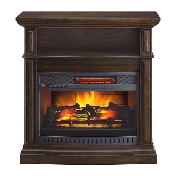
Middleton 32" Fireplace Console
If you have any questions regarding assembly or if parts are missing, DO NOT return this item to the
store where it was purchased. Please call our toll-free customer service number and have your
instructions and parts list ready to provide the model name, part name or factory number:
Or visit our website 24 H a day, 7 days a week for product assistance at
THIS INSTRUCTION BOOKLET CONTAINS IMPORTANT SAFETY INFORMATION.
Model # WSF32WV23-DB
# WSF32WV23-WA
ADULT ASSEMBLY REQUIRED
Pacific Standard Time: 8:30 a.m. - 4:30 p.m., Monday - Friday
www.whalenfurniture.com
Or e-mail your request to:
PLEASE READ AND KEEP FOR FUTURE REFERENCE.
Date 2018-06-12 Rev. 0001-A Factory: GALFUR
1-866-942-5362
parts@whalenfurniture.com
LOT NUMBER:
DATE PURCHASED: /
/
Advertisement

Related Manuals for Whalen Middleton WSF32WV23-DB


Summary of Contents for Whalen Middleton WSF32WV23-DB
- Page 1 LOT NUMBER: DATE PURCHASED: / Middleton 32” Fireplace Console Model # WSF32WV23-DB # WSF32WV23-WA ADULT ASSEMBLY REQUIRED If you have any questions regarding assembly or if parts are missing, DO NOT return this item to the store where it was purchased. Please call our toll-free customer service number and have your instructions and parts list ready to provide the model name, part name or factory number: 1-866-942-5362 Pacific Standard Time: 8:30 a.m.
-
Page 2: Special Note
M A X I M U M R E C O M M E N D E D W E I G H T L O A D S MANUFACTURER: Whalen Furniture Manufacturing CATALOG: Middleton 32” Fireplace Console MODEL # WSF32WV23-DB / WSF32WV23-WA MADE IN CHINA FITS UP TO MOST 99.06 cm / 39”... - Page 3 IMPORTANT Before you begin: Open, identify and count all parts prior to assembly. Lay out parts on a flat and non- abrasive surface. You will need the parts identified on page 4 and 5 of this instruction manual. NOTE: IT IS VERY IMPORTANT TO USE GLUE WITH THE DOWELS. EXCESS GLUE CAN BE WIPED OFF WITH A DAMP CLOTH.
-
Page 4: Parts And Hardware List
Parts and Hardware List Please read completely through the instructions and verify that all listed parts and hardware are present before beginning assembly. A- Top Panel (Qty. 1) B- Base (Qty. 1) C- Center Shelf (Qty. 1) D- Upper Side Panel (Qty. 2) E- Lower Left Side Panel (Qty. - Page 5 Parts and Hardware List Please read compl etely through the instructions and verify that all list ed parts and hardware are present before beginning assembly. (1) Cam Lock (2) Cam Bolt (3) 8 mm x 30 mm Wood Dowel (Qty. 16+1 extra) (Qty.
- Page 6 Assembly Instructions 1. Unpack the unit and confirm that you have all the hardware and required parts. Assemble the unit on a carpeted floor or the empty carton to avoid any scratch. 2. Securely screw the Cam Bolts (2) into the designated plastic bushings on the Top Panel (A), the Base (B) and the Center Shelf (C) using a Phillips screwdriver.
- Page 7 Assembly Instructions 5. Glue two Wood Dowels (3) into the inner holes of the Middle Crossbar (G) and attach it to the front edge of the Center Shelf (C) with three 63 mm Flat Head Screws (6). 6. Attach the previous assembly (C and G) to Lower Side Panels (E and F) with six Wood Dowels (3) and four Cam Locks (1).
- Page 8 Assembly Instructions 7. Ask for assistance to stand the unit upright. Securely screw four Cam Bolts (2) into the plastic bushings on the Center Shelf (C). 8. Attach the Upper Side Panels (D) to the Center Shelf (C) with six Wood Dowels (3) and four Cam Locks (1).
- Page 9 Assembly Instructions 9. Attach Top Panel (A) to the Upper Side Panels (D) with six Wood Dowels (3) and four Cam Locks (1). 10. Turn the assembled unit at its front edges. 11. With the pilot holes as a guide, fasten two Straight Metal Brackets (7) at the joints where Middle Crossbar (G) meets the Lower Side Panels (E and F), using two 12 mm Flat Head Screws (4) per bracket.
- Page 10 Assembly Instructions 12. Now, go back and securely tighten all the Cam Locks and Wood Screws. Make sure all the parts are tight and there are no gaps between the parts. This will help keep the unit square. 13. Pick up the Upper Back Panel (H) and align the drilled holes with pilot holes on the back stretcher of the Top Panel (A).
- Page 11 Assembly Instructions 16. Lift the fireplace insert carefully into the back of the assembled mantel and center it in the opening. DO NOT drag the insert across the Base (B) as it may scratch the unit. The rubber bumper is against the firebox 17.
- Page 12 Assembly Instructions NOTE: To prevent your TV from tipping, you must follow these instructions if you place a TV on top of your console. Otherwise, skip to “Step 20”. 19. Remove the paper backing from the Acrylic Stopper (13), then properly align the Acrylic Stopper into the cut-out on the acrylic stopper template on the Top Panel (A).
- Page 13 Assembly Instructions Tools required: Phillips screwdriver, stud finder, power drill and 1/8” drill bit. 21. Position the console at the desired location against a wall. If necessary, adjust the pre-attached floor levelers until the unit is level. 22. Follow the instructions printed on the plastic bag containing the tipping restraint hardware to attach the tip-over restraints to the unit and the wall.
-
Page 14: Care And Maintenance
Should this product be defective in workmanship or materials or fail under normal use, we will repair or replace it for up to one (1) year from date of purchase. Every Whalen Furniture product is designed to meet your highest expectations. We guarantee that you will immediately see the value of our fine furniture.
Need help?
Do you have a question about the Middleton WSF32WV23-DB and is the answer not in the manual?
Questions and answers