Table of Contents
Advertisement
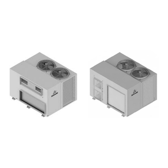
Package Commercial Units
Installation and Commissioning Guide
Under/Over Unit
PACKAGE MODELS
UNDER/OVER
CONFIGURATION
PCG153U*
PCA300U*
PCG153V**
PCG173U*
PCA330U*
PCG173V**
PCG203U*
PCG330U*
PCG203V**
PCG233U*
PCA340U*
PCG233V**
PCG260U*
PCG340U*
PCG260V**
PCG290U*
PCG400U*
PCG290V**
Above images shown are for illustration purposes only.
•
LH Air Handing Option
• •
RH Air Handing Option
* Under - Over Indoor Coil / Fan Arrangement
** Vertical Discharge Evaporator
IMPORTANT NOTE:
Please read this manual carefully before installing or operating your air conditioning unit.
SIDE BY SIDE
CONFIGURATION
•
PCA300V**
PCG290L
PCG290R
•
PCA330V**
PCG300L
PCG300R
•
PCG330V**
PCG330L
PCG330R
•
PCA340V**
PCG340L
PCG340R
•
PCG340V**
PCG400L
PCG400R
PCG400V**
Left Hand Air Handing Unit
••
••
PKA300T-LFFT-EA
••
••
PKA300T-RFFT-EA
••
••
••
Advertisement
Table of Contents

Related Manuals for ActronAir PCG153U Series


Summary of Contents for ActronAir PCG153U Series
- Page 1 Package Commercial Units Installation and Commissioning Guide Under/Over Unit Left Hand Air Handing Unit PACKAGE MODELS UNDER/OVER SIDE BY SIDE CONFIGURATION CONFIGURATION •• • •• PCG153U* PCA300U* PCG153V** PCA300V** PKA300T-LFFT-EA PCG290L PCG290R • •• •• PCG173U* PCA330U* PCG173V** PCA330V** PKA300T-RFFT-EA PCG300L PCG300R •...
-
Page 2: Table Of Contents
Package Commercial Unit Installation and Commissioning Guide Table of Contents 01. Inspections ..........................3 01.01. Information About This Guide 01.02. Product Inspections 01.03. Codes, Regulations and Standards 01.04. Important Safety Symbols And Labels 02. General Information ........................3 03. Safety Instructions ........................5 04. -
Page 3: Inspections
Check your air conditioning unit and all items against the invoice upon receiving your shipment. Inspect the unit, components and accessories for any sign of damage. If there is any damage to the unit, contact ActronAir Customer Care Department immediately on: 1300 522 722 to obtain a Goods Return Number. - Page 4 Hydrophilic blue coil fins provide protection to your heat exchangers and enhanced heat transfer with increased performance efficiency. System Flexibility The ActronAir air conditioning units are the first choice for residential, office, schools and other air conditioning facilities applications, both for new construction or retrofitting projects. Sustainability and Environmentally Friendly The air conditioning system is supplied with zero ozone depleting R-410A refrigerant, which has no phase out or replacement concern.
-
Page 5: Safety Instructions
Package Commercial Unit Installation and Commissioning Guide 03. Safety Instructions • Only licensed HVAC technicians* should install and service this air conditioning equipment. Improper service or alteration by an unqualified technician could result in significant and major damage to the product or property which may render your warranty null and void. -
Page 6: Installation Instructions
Package Commercial Unit Installation and Commissioning Guide 04. Installation Instructions All service technicians handling refrigerant must be licensed to handle refrigerant gases. Recover and Recycle Refrigerants Never release refrigerant to the atmosphere! It is an offence in Australia to do so. Always recover, recycle and reuse refrigerants. -
Page 7: Operation Manual Access
TUBE ENDS MUST BE ROUND AND OF FULL DIAMETER. FOLD 0.5 / m Installation and Commissioning Guide - Package Commercial Unit ActronAir Pty Ltd This drawing always remains the ANGLES & SQUARENESS TUBE MUST BE CLEAN AND FREE FROM 5 Irvine Place... -
Page 8: Unit Dimensions
3. Minimum service access areas and spaces for airflow clearances are responsibilities of the installer, ActronAir will not be held liable for any extra charges incurred due to lack of access and space for airflow. - Page 9 3. Minimum service access areas and spaces for airflow clearances are responsibilities of the installer, ActronAir will not be held liable for any extra charges incurred due to lack of access and space for airflow.
- Page 10 1000mm between the units or between the unit and the outside perimeter is available. 3. Minimum service access areas and spaces for airflow clearances are responsibilities of the installer, ActronAir will not be held liable for any extra charges incurred due to lack H-SD of access and space for airflow.
- Page 11 3. Minimum service access areas and spaces for airflow clearances are responsibilities of the installer, ActronAir will not be held liable for any extra charges incurred due to lack of access and space for airflow.
-
Page 12: Left Handing Units
3. Minimum service access areas and spaces for airflow clearances are responsibilities of the installer, ActronAir will not be held liable for any extra charges incurred due to lack of access and space for airflow. -
Page 13: Right Handing Units
3. Minimum service access areas and spaces for airflow clearances are responsibilities of the installer, ActronAir will not be held liable for any extra charges incurred due to lack of access and space for airflow. -
Page 14: Clearances And Weights
Package Commercial Unit Installation and Commissioning Guide 08. Clearances and Weights DUCT WORK ID COIL INDOOR INDOOR Service Clearance Service NOTES Clearance Airflow (Compressor • Model PCA300U is shown for illustration Allowance COMP purposes only. Electrical • Under all circumstances, Condenser Air must COMP Control) not recirculate back onto Condenser Coil. -
Page 15: Banking Of Units
• Minimum service access areas and spaces for airflow clearances are responsibilities of the installer, ActronAir will not be held liable for any extra charges incurred due to lack of access and space for airflow. - Page 16 Package Commercial Unit Installation and Commissioning Guide Cluster Configuration Airflow Allowance Service Clearances Airflow (Compressor and Electricals + Fan) Allowance OUTDOOR COIL OUTDOOR COIL UNIT 1 UNIT 3 Duct Duct Work Work Unit 2 COMP COMP Service Unit 3 Clearance Airflow (Comp.
-
Page 17: Unit Lifting Procedure
Package Commercial Unit Installation and Commissioning Guide 10. Unit Lifting Procedure WARNING WH&S regulations must be observed and will take precedence during lifting process. Crane Lifting Method Crane lifting method is recommended for high rise lifting. Connect the loop ends of slings into shackle Provide rubber pads to prevent damage... - Page 18 Package Commercial Unit Installation and Commissioning Guide PROCEDURE: 1. Slip nylon slings through the pallet as shown in Fig. 1. 2. Use a Bow or Dee shackle to connect the slings. 3. Ensure slings are protected by rubber pads or similar if slings are draped across unit edges, corners, or air grilles. This will prevent the unit from being damaged during lifting.
-
Page 19: Condensate And Safety Tray Drainage Instructions
Package Commercial Unit Installation and Commissioning Guide 11. Condensate and Safety Tray Drainage Instructions NOTES • PCG model shown for illustration purposes only. • Suggested condensate drainage connection and OUTDOOR COIL details are also applicable to PCA models. • Ensure that Condenser and Evaporator condensate Condensate drains are connected separately. -
Page 20: Electrical Installation
Package Commercial Unit Installation and Commissioning Guide 12. Electrical Installation All electrical work must be carried out by a qualified technician. Make sure all wiring is in accordance with local wiring rules. Wiring connections should be made in accordance with the wiring diagram provided. DANGER Live Electrical Supply ! •... -
Page 21: Package Unit Electrical Connection
Package Commercial Unit Installation and Commissioning Guide 13. Package Unit Electrical Connection DETAILED WIRING DIAGRAM IS PROVIDED WITH THE UNIT Condenser Side: Located at the back of electrical/compressor access panel. MAINS WIRING (400 VAC) ( Three Phase +Neutral+Earth) 50Hz DATA CABLE TO WALL CONTROL (2 Core 14/0.20 0.44mm Shielded Data Cable) SUB-MAINS CIRCUIT BREAKER... -
Page 22: Maximum Cable Length
Master Controller to Remote Sensor (Max. of 2 Optional Sensors) 50 m each *Total Cumulative length of all the aggregate cable lengths must not exceed 500 meters. Consult ActronAir for longer cable length requirement. Installation and Commissioning Guide - Package Commercial Unit... -
Page 23: Standard Indoor Fan Commissioning
Package Commercial Unit Installation and Commissioning Guide 15. Standard Indoor Fan Commissioning Models: PCA300U/V PCA330U/V PCA340U/V CAUTION • Commissioning of indoor fan should be carried out by a qualified / licensed installer or service technician. • Make sure that all instructions are followed accordingly. •... - Page 24 Package Commercial Unit Installation and Commissioning Guide NOTE When the Indoor Fan DIP switch setting on the Condenser CPU Board is set to SINGLE SPEED INDOOR FAN , the Indoor Fan output on the Condenser CPU Board is always from the HIGH terminal output. Step 3.
-
Page 25: Ec Indoor Fan Commissioning
INCORRECT WIRING VOIDS WARRANTY CPI3-2 S/N: XXXXXXXX CPI 3 23787-3 ActronAir 240VAC IN ON/OFF (CPI3-2) COMMERCIAL PWM INDOOR BOARD Step 3. Using the fan table provided below, select the corresponding fan %PWM by plotting the external static pressure requirement (duct static pressure) and nominal airflow requirement of the unit. (Data may need to be calculated to get the desired value). -
Page 26: Pcg260U/V To Pcg400U/V/L/R Add Pka300T-L/R
ADJUST V1.0 ADJUSTMENT DAMAGE DUE TO (POTENTIOMETER) INCORRECT WIRING VOIDS WARRANTY 240VAC OUT CPI 3 23787-3 ActronAir 240VAC IN ON/OFF (CPI3-1) COMMERCIAL PWM INDOOR BOARD Installation and Commissioning Guide - Package Commercial Unit Doc. Part No. 0525-055 Ver. 9 220308... - Page 27 Package Commercial Unit Installation and Commissioning Guide Step 3. Using the fan table provided below, select the corresponding fan %PWM by plotting the external static pressure requirement (duct static pressure) and nominal airflow requirement of the unit. (Data may need to be calculated to get the desired value).
-
Page 28: Indoor Fan Table And Fan Curve
Performance Fan Curve shown is at Dry Coil Condition. Airflow PCG173U/V CPI 3 should be reduce with respect to the moisture content in the 23787-3 ActronAir 240VAC IN ON/OFF PCG203U/V air. All data provided does not include filters. Please review filter... -
Page 29: Pcg173U/V
Performance Fan Curve shown is at Dry Coil Condition. Airflow PCG173U/V CPI 3 should be reduce with respect to the moisture content in the 23787-3 ActronAir 240VAC IN ON/OFF PCG203U/V air. All data provided does not include filters. Please review filter... -
Page 30: Pcg203U/V
Performance Fan Curve shown is at Dry Coil Condition. Airflow PCG173U/V CPI 3 should be reduce with respect to the moisture content in the 23787-3 ActronAir 240VAC IN ON/OFF PCG203U/V air. All data provided does not include filters. Please review filter... -
Page 31: Pcg233U/V
CPI3-2 S/N: XXXXXXXX Performance Fan Curve shown is at Dry Coil Condition. Airflow PCG173U/V CPI 3 23787-3 ActronAir should be reduce with respect to the moisture content in the 240VAC IN ON/OFF PCG203U/V NOTES: air. All data provided does not include filters. Please review filter PCG233U/V LED will show PWM without %. -
Page 32: Pcg260U/V
Performance Fan Curve shown is at Dry Coil Condition. Airflow 240VAC OUT PCG300L/R CPI 3 23787-3 should be reduce with respect to the moisture content in the ActronAir PKA300L/R 240VAC IN ON/OFF air. All data provided does not include filters. Please review filter NOTES: SCG290E manufacturer for application. -
Page 33: Pcg290U/V/L/R
Performance Fan Curve shown is at Dry Coil Condition. Airflow 240VAC OUT PCG300L/R CPI 3 23787-3 should be reduce with respect to the moisture content in the ActronAir PKA300L/R ON/OFF 240VAC IN air. All data provided does not include filters. Please review filter NOTES: SCG290E manufacturer for application. -
Page 34: Pcg300L/R
Performance Fan Curve shown is at Dry Coil Condition. Airflow 240VAC OUT PCG300L/R CPI 3 23787-3 should be reduce with respect to the moisture content in the ActronAir 240VAC IN PKA300T-L/R ON/OFF air. All data provided does not include filters. Please review filter NOTES: SCG290E manufacturer for application. -
Page 35: Pka300T - L/R
Performance Fan Curve shown is at Dry Coil Condition. Airflow 240VAC OUT PCG300L/R CPI 3 23787-3 should be reduce with respect to the moisture content in the ActronAir ON/OFF 240VAC IN PKA300T-L/R air. All data provided does not include filters. Please review filter NOTES: SCG290E manufacturer for application. -
Page 36: Pcg330U/V
Performance Fan Curve shown is at Dry Coil Condition. Airflow 240VAC OUT PCG300L/R CPI 3 23787-3 should be reduce with respect to the moisture content in the ActronAir 240VAC IN PKA300T-L/R ON/OFF air. All data provided does not include filters. Please review filter NOTES: SCG290E manufacturer for application. -
Page 37: Pcg330L/R
Performance Fan Curve shown is at Dry Coil Condition. Airflow 240VAC OUT PCG300L/R CPI 3 23787-3 should be reduce with respect to the moisture content in the ActronAir 240VAC IN PKA300T-L/R ON/OFF air. All data provided does not include filters. Please review filter NOTES: SCG290E manufacturer for application. -
Page 38: Pcg340U/V
Performance Fan Curve shown is at Dry Coil Condition. Airflow 240VAC OUT PCG300L/R CPI 3 23787-3 should be reduce with respect to the moisture content in the ActronAir 240VAC IN ON/OFF PKA300T-L/R air. All data provided does not include filters. Please review filter NOTES: SCG290E manufacturer for application. -
Page 39: Pcg340L/R
Performance Fan Curve shown is at Dry Coil Condition. Airflow 240VAC OUT PCG300L/R CPI 3 23787-3 should be reduce with respect to the moisture content in the ActronAir 240VAC IN ON/OFF PKA300T-L/R air. All data provided does not include filters. Please review filter NOTES: SCG290E manufacturer for application. -
Page 40: Pcg400U/V/L/R
Performance Fan Curve shown is at Dry Coil Condition. Airflow 240VAC OUT PCG300L/R CPI 3 23787-3 should be reduce with respect to the moisture content in the ActronAir 240VAC IN ON/OFF PKA300T-L/R air. All data provided does not include filters. Please review filter NOTES: SCG290E manufacturer for application. -
Page 41: Refrigerant Charging
Package Commercial Unit Installation and Commissioning Guide 18. Refrigerant Charging • The units detailed on this guide are factory charged with R-410A refrigerant. Should there be need to add or remove refrigerant, it is recommended to follow the charging method explained below. •... - Page 42 Package Commercial Unit Installation and Commissioning Guide SUBCOOLING AND SUPERHEAT CHARGING METHOD Parameters: LLT = Liquid Line Temperature SLT = Suction Line Temperature SCT = Saturated Condensing Temperature SST = Saturated Suction Temperature Cooling and Heating Operation: Adjust the refrigerant charge to obtain the correct superheat and subcooling for optimal performance as follows: 1.
- Page 43 Package Commercial Unit Installation and Commissioning Guide Checking for Superheat: Maintaining the correct superheat is important for ensuring the evaporator is achieving maximum capacity and avoiding excessive liquid refrigerant returning to the compressor. 1. From the R-410A Pressure/Temperature Chart record the corresponding Saturated Suction Temperature (SST) at the given suction pressure.
- Page 44 Package Commercial Unit Installation and Commissioning Guide R-410A PRESSURE / TEMPERATURE CHART Temp Pressure Temp Pressure Temp Pressure Temp Pressure °C °C °C °C -34.4 194.9 805.9 2090.7 -30.7 206.9 834.1 2145.5 -26.8 219.2 862.9 2201.3 -22.8 231.9 892.6 2258.2 -18.6 245.1 922.8...
-
Page 45: Maintenance
Package Commercial Unit Installation and Commissioning Guide 19. Maintenance This section describes the procedure that must be performed as a part of normal maintenance program. Regular servicing of equipment by licensed technician is highly recommended. Regular servicing of your unit helps in maintaining its optimum performance and reliability. -
Page 46: Maintenance Frequency Checklist
Package Commercial Unit Installation and Commissioning Guide DANGER No Water into the Drive! Ensure consideration is given to the possibility of water entering the electrical compartments during cleaning of the condenser coil. Coil Cleaning Procedures • Disconnect power to the unit. •... - Page 47 Package Commercial Unit Installation and Commissioning Guide INDOOR SECTION Service Period Parts Detail of Service Check Service Methods Mths Mths For highly corrosive environment, wash panels Casing / Panels Visual check for damage, rust quarterly with water and neutral and Frames and dust accumulation.
- Page 48 Package Commercial Unit Installation and Commissioning Guide OUTDOOR SECTION Service Period Parts Detail of Service Check Service Methods Mths Mths For highly corrosive environment, wash panels Casing / Panels Visual check for damage, rust quarterly with water and neutral and Frames and dust accumulation.
-
Page 49: Key Components List
Package Commercial Unit Installation and Commissioning Guide 21. Key Components List PART DESCRIPTION NUMBER 1560-440 1560-463 1560-462 1560-471 Compressor 1560-436 1560-437 1560-438 1560-459 2025-006 Crankcase Heater 2025-005 2505-109 2505-130 Outdoor Fan 2505-106 2505-134 2520-338 2520-340 2520-313 Indoor Fan 2520-329 2520-324 2520-327 2020-151 2020-097... - Page 50 Package Commercial Unit Installation and Commissioning Guide PART DESCRIPTION NUMBER HP Switch 2060-019 LP Switch 2060-020 Metering Device - (0.0591”) Piston 4540-059 Metering Device - (0.0610”) Piston 4540-061 Metering Device - (0.065 ”) Piston 4540-065 Metering Device - (0.0670”) Piston 4540-067 Metering Device - (0.0689”) Piston 4540-068...
- Page 51 Package Commercial Unit Installation and Commissioning Guide PART PCG290L PCG300L PCG330L PCG340L PCG400L PKA300T-L DESCRIPTION NUMBER PCG290R PCG300R PCG330R PCG340R PCG400R PKA300T-R 1560-437 1560-440 Compressor 1560-438 1560-463 1560-459 2025-006 Crankcase Heater 2025-005 2505-106 Outdoor Fan 2505-134 2520-029 Indoor Fan 2520-326 2020-097 Outdoor Control Board 2020-045...
-
Page 52: Start Up And Commissioning Report
Package Commercial Unit Installation and Commissioning Guide 22. Start Up and Commissioning Report INSTALLATION INFORMATION Name: Tel. Number: CUSTOMER Address: Name: Tel. Number: INSTALLER Address: Site Address: Date Installed: Model: Serial Number: CIRCUIT TEMPERATURE SETTINGS AND AMBIENT TEMPERATURE SYSTEM 1 SYSTEM 2 °C °C... - Page 53 THIS PAGE WAS INTENTIONALLY LEFT BLANK...
- Page 54 THIS PAGE WAS INTENTIONALLY LEFT BLANK...
- Page 55 THIS PAGE WAS INTENTIONALLY LEFT BLANK...
- Page 56 ©Copyright 2022 Actron Engineering Pty Limited ABN 34 002767240. ®Registered Trade Marks of Actron Engineering Pty Limited. ActronAir is constantly seeking ways to improve the design of its products, therefore specifications are subject to change without notice. Installation and Commissioning Guide - Package Commercial Unit...
Need help?
Do you have a question about the PCG153U Series and is the answer not in the manual?
Questions and answers