
Related Manuals for KUHN GA6501


Summary of Contents for KUHN GA6501
- Page 1 OPERATOR'S MANUAL KN255AGB F Read carefully before starting the machine Gyrorake Original instructions - English - 08-2015 KN255AGB F...
-
Page 3: Dear Owner
Nevertheless, the service life depends highly on the conditions of use (products to handle, soil, weather conditions, etc...). Designated use of the machine The GA6501 Gyrorake must only be used for the work for which it has been designed: raking on the ground and forming windrows of pre-mowed fodder and straw. Document illustrations The illustrations in this manual may be based on one type of machine only. -
Page 4: Table Of Contents
Gyrorake GA6501 2. Contents Dear Owner ........................1 Contents ..........................2 Identification of the machine..................5 Front view (working position) ......................5 Rear view (transport position) ......................5 Model identification plate ......................... 6 Optional equipment.......................... 6 Safety..........................7 Description of symbols used in this document................. 7 Safety instructions ........................... - Page 5 Gyrorake GA6501 Machine specifications....................23 Description and glossary ....................... 23 Technical specifications ......................... 24 Compulsory equipment........................25 5.3.1 Check chain (Belgium, Spain, France) ................25 5.3.2 Lighting and signalling...................... 25 Sound levels ..........................26 Putting into service...................... 27 Description of control elements ..................... 27 Coupling and uncoupling .......................
- Page 6 Gyrorake GA6501 Optional equipment......................47 Steering system ..........................47 9.1.1 Steering system adjustment ..................... 47 9.1.2 Lubrication ........................49 Check chains ..........................50 Clearance lights ..........................50 SMV sign ............................50 Europe signalling equipment ......................51 9.5.1 Coupling and uncoupling ....................51 USA signalling equipment......................
-
Page 7: Identification Of The Machine
Gyrorake GA6501 3. Identification of the machine Front view (working position) Rear view (transport position) 3. - Identification of the machine KN255AGB F... -
Page 8: Model Identification Plate
Gyrorake GA6501 Model identification plate Please write below the type and serial number of the machine. This information is to be given to the Kuhn authorized dealer for any spare parts order or warranty claim. KUHN S.A. 67700 SAVERNE - FRANCE... -
Page 9: Safety
Gyrorake GA6501 4. Safety Description of symbols used in this document This symbol indicates a potentially hazardous situation that if not avoided, could result in serious bodily injury. This symbol is used to identify special instructions or procedures which, if not followed strictly, could result in machinery damage. -
Page 10: Safety Instructions
Never let anyone operate the machine who is not trained to do so. Should you have any difficulties in understanding any parts of this manual, please contact your KUHN dealer. 4.2.3 Precautions to be taken before carrying out any operations on the machine... -
Page 11: Precautions To Take Before Using The Machine
Gyrorake GA6501 4.2.4 Precautions to take before using the machine Do not wear loose clothing which could become caught up in moving parts. Wear the appropriate protective clothing for the work in hand (gloves, shoes, goggles, helmet, ear defenders, etc.). -
Page 12: Precautions When Driving On Public Roads
Gyrorake GA6501 4.2.6 Precautions when driving on public roads Dimensions Depending on the dimensions of the machine, contact the relevant authorities to ensure that it can be legally transported on public roads. If the machine is over the maximum legal size, follow the local regulations for special transportation of oversize equipment. -
Page 13: Maximum Speed
Gyrorake GA6501 Lights and indicators Before transporting the machine on public roads, ensure that all legally required lightings and signallings are in place. Ensure that lightings and signallings are clean and in good working order. Replace any missing or broken equipment. -
Page 14: Precautions When Coupling
Gyrorake GA6501 4.2.8 Precautions when coupling Before attaching the machine, make sure that it cannot accidentally start moving (chock the wheels) and that the parking stand is in the right position. The machine must only be attached to the hitch points provided for this purpose. -
Page 15: Pto Shaft
Gyrorake GA6501 4.2.10 PTO shaft Use only PTO shafts supplied with the machine or recommended by the machine manufacturer. The protective shield of the tractor PTO stub, the PTO shaft guards and the protective shield of the machine input shaft must always be in place and in good condition. -
Page 16: Precautions During Manoeuvres
Gyrorake GA6501 Do not install any adapter device that results in a portion of the tractor PTO stub, the rotating PTO shaft, or the adapter to be unguarded. The tractor master shield shall overlap the end of the splined shaft and the added adaptor device as outlined in the table. -
Page 17: Remote Controlled Components
Gyrorake GA6501 4.2.12 Remote controlled components Danger of crushing and shearing can exist when components are operated by hydraulic or pneumatic controls. Keep away from these danger zones. 4.2.13 Tyres Regularly check the tyre pressure. Respect manufacturers' recommendations on pressure. -
Page 18: Precautions For Maintenance And Repair Work
Gyrorake GA6501 4.2.16 Precautions for maintenance and repair work Before leaving the tractor or before adjusting, maintaining or repairing the machine, disengage the PTO drive, turn off the engine, remove ignition key and wait until all moving parts have come to a complete stop and apply park brake. -
Page 19: Precautions For Machine Use
Gyrorake GA6501 4.2.18 Precautions for machine use Before using the machine, check tools (tines) and their attachment hardware in accordance with the instructions of the present manual. Check the guards regularly. Immediately replace any damaged or missing elements. Before engaging the pto drive, lower the rotors onto the ground. -
Page 20: Location And Description Of Safety Decals On The Machine
Gyrorake GA6501 Location and description of safety decals on the machine 4.3.1 Location of safety decals 4. - Safety KN255AGB F... -
Page 21: Description Of Safety Decals
Gyrorake GA6501 4.3.2 Description of safety decals Operating instructions (1) The operators' manual contains all the information necessary for using the machine safely. It is imperative to read and comply with all instructions. Working on the machine (2) - Page 22 Gyrorake GA6501 Rotary tools (4) To prevent entanglement keep a safe distance from the machine. Body crushing (5) Stay a safe distance from the machine. Crushing hazard. 4. - Safety KN255AGB F...
-
Page 23: Road Safety Equipment And Recommendations
Road safety equipment and recommendations The road safety equipment is mounted in the factory or by your authorized Kuhn dealer according to current safety regulations. - Always keep to the legal speed limit for driving a tractor-machine assembly on public roads. -
Page 24: Tyre Pressure
Gyrorake GA6501 The side device is made up of the following components: • 2 self-adhesive reflectors (1) per machine side. 4.4.1 Tyre pressure • Transport wheels (1): 2.0 bar (29 psi). • Rotor wheels (2): 2.0 bar (29 psi). 4.4.2 Instructions specific to France ... -
Page 25: Machine Specifications
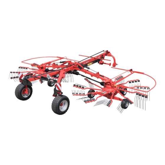
Gyrorake GA6501 5. Machine specifications Description and glossary Parking stand Rotor arm Rotor arm folding cylinder Transport lock Transport wheel Headstock Main frame Tine Tine arms Stub axle 10 : Oscillating shaft housing Outer guard 11 : 12 : Rotor 13 : 5. -
Page 26: Technical Specifications
Gyrorake GA6501 Technical specifications GA6501 Attachment type 2 point, Category 2 Number of rotors Number of arms per rotor Working width (DIN11220) from 5.40 to 6.40 m (17’8’’ - 21’) (approximately) Swath width from 1.00 to 2.00 m (3’3’’ - 6’6’’) (approximately) Length in working position 5.15 m (16’11’’) -
Page 27: Compulsory Equipment
Gyrorake GA6501 Compulsory equipment 5.3.1 Check chain (Belgium, Spain, France) The safety chain is intended to keep the machine under control in the event of a loss or failure of the hitch pin. 5.3.2 Lighting and signalling • Europe signalling equipment. -
Page 28: Sound Levels
Gyrorake GA6501 Sound levels Sound levels have been measured in accordance with the measuring methods as defined in: • NF EN ISO 4254-1 «Agricultural machinery - Safety - Part 1: General requirements» Weighted equivalent continuous acoustic pressure level at the driver's seat (closed cabin) L (A) eq: •... -
Page 29: Putting Into Service
Gyrorake GA6501 6. Putting into service Description of control elements The machine is fitted with the following components: • 2 rotor arm release cords, accessible from the tractor cab. • 1 36 mm flat spanner. • Adjustment crank handle. Coupling and uncoupling 6.2.1 Description of coupling elements... -
Page 30: Preparing The Tractor
Gyrorake GA6501 6.2.2 Preparing the tractor Check that the tractor's authorized gross weight as well as its lift capacity and maximum weight per axle are not exceeded: See section: - Safety / Safety instructions / Precautions when driving on public roads. - Page 31 Gyrorake GA6501 Position the machine on level hard ground. Tyre pressure - Check tyre pressure (Left side = Right side). Hitch pin parallelism - Adjust tractor lift rods so that hitch pins are parallel to the ground. ...
-
Page 32: Coupling The Machine
Gyrorake GA6501 6.2.3 Coupling the machine - Lower the tractor three-point linkage. - Insert lower links on hitch pins on both machine sides (a). - Secure each lower link with lynch pin (b). - Use lower linkage arm stabilizers. - Raise tractor lift linkage to free parking stand. -
Page 33: Hydraulic Connection
Gyrorake GA6501 6.2.4 Hydraulic connection - Connect hydraulic hoses transport/work cylinders to a double acting valve. 6.2.5 Electrical connection - Connect 7-pin plug to the tractor. 6. - Putting into service KN255AGB F... -
Page 34: Primary Pto Shaft
Gyrorake GA6501 6.2.6 Primary PTO shaft Before using the machine for the first time: - Grease the transmission. Check overlap of the u-joint drive shaft and adjust length if necessary to avoid any premature wear. The direction of rotation is shown on a decal. - Page 35 Gyrorake GA6501 Never operate the PTO shaft at an angle X exceeding 30°. To avoid serious accidents, the PTO drive shaft guards must be properly in place and fixed with the chains provided. - Attach PTO shaft guard chain in hole (1) on machine side.
-
Page 36: Adjusting The Machine
Gyrorake GA6501 6.2.7 Adjusting the machine Frame height If the machine is fitted with check chains: (Belgium, Spain, France) - Lower the tractor lift in order to obtain a distance slightly over H = 500 mm (1’8’’) between the hitch pins and the ground. -
Page 37: Uncoupling The Machine
Gyrorake GA6501 6.2.8 Uncoupling the machine Park the machine on an even fairly level ground. - Block machine with wheel chocks (1). - Lower and lock parking stand (1). Only for: (Belgium, Spain, France). - Remove check chains on tractor side. - Page 38 Gyrorake GA6501 - Pivot foldable guards outwards. - Lock guard with lynch pin (1). The machine is uncoupled. 6. - Putting into service KN255AGB F...
-
Page 39: Instructions For Transport
Gyrorake GA6501 7. Instructions for transport Before placing the machine into transport position: - Wait until the rotating parts have come to a complete stop. - Check that nobody is within the machine pivoting area. - If there is someone, make sure the person moves away. - Page 40 Gyrorake GA6501 - Shut-off valve (1). The machine is in transport position. Never engage the tractor PTO drive when the machine is in transport position. 7. - Instructions for transport KN255AGB F...
-
Page 41: Conformity With The Road Regulations
Gyrorake GA6501 Conformity with the road regulations Before driving the machine on public roads, ensure that the machine complies with current highway code regulations. - Check that the light boards are clean and that the lighting equipment functions before transporting the machine on public roads. -
Page 42: Instructions For Work
Gyrorake GA6501 8. Instructions for work Before placing the machine in working position: - Check that nobody is within the machine pivoting area. - If there is someone, make sure the person moves away. Putting the machine into work position From the transport position: - Open the valve (1). -
Page 43: Adjustments In Working Position
Gyrorake GA6501 Adjustments in working position Before making any adjustment: - Check that nobody is within the machine pivoting area. - If there is someone, make sure the person moves away. 8.2.1 Working width From the working position: - Raise machine using tractor lift linkage so that wheels are no longer in contact with the ground. - Page 44 Gyrorake GA6501 - Using crank (1), adjust working width. - Align mark corresponding to the required working width with mark (2). Position a: Working width: 5.40 m (17’8’’). Position b: Working width: 5.60 m (18’4’’). Position c: Working width: 5.80 m (19’).
-
Page 45: Rotor Working Height
Gyrorake GA6501 - Open the valve (1). - Lower the machine on the ground. 8.2.2 Rotor working height From the working position: A too low rotor height causes: • An excessive tine wear. • Crop being contaminated by soil. • Delay in regrowth. - Page 46 Gyrorake GA6501 - Pull crank (1) out of its holder. - Turn crank (1) to increase or reduce distance D between tines and ground. - Place crank in its holder. In addition to the adjustment per crank, the wheel height can be adjusted to modify the rotor horizontality: - Loosen the counter nuts and screws (1).
-
Page 47: Machine Use
Gyrorake GA6501 Machine use Before working: - Fold rotor guards. - Keep all persons and animals away from the machine danger zone. The machine is designed to form a central windrow adjustable in width. - Place the machine in working position. -
Page 48: Putting The Machine In Headland Turn Position
Gyrorake GA6501 8.3.1 Putting the machine in headland turn position The machine is placed from working position into headland turn position by means of the rotor arm lift cylinders controled as from a tractor's hydraulic outlet. - Use the headland turn position when crossing over an already formed windrow. -
Page 49: Optional Equipment
Gyrorake GA6501 9. Optional equipment Steering system Kit no. 1146510 This equipment enables: • Facilitate headland turn manoeuvres and speed up its realignment with regards to a machine not equipped with this device. • drive onto a field difficult to access. - Page 50 Gyrorake GA6501 Adjusting the wheel alignment: - Loosen the check nut (1). - Remove pin (2). - Remove pin (3). - Position wheel (4) parallel to wheel (5). - Adjust bracket (6) using nut (7). - Reinstall pin (3). - Reinstall pin (2).
-
Page 51: Lubrication
Gyrorake GA6501 9.1.2 Lubrication Lubrication intervals are indicated for normal conditions of use. 1 time per week Every 200 hours Lubrication Grease: - The steering system pivot points. Oil: - Link rod pivot pins. Grease Lubricate with multi-purpose grease grade NLGI 2. -
Page 52: Check Chains
Gyrorake GA6501 Check chains Kit no. 1146820 Check chains allow tractor lift linkage stabilization and ensure a fixed frame height Clearance lights Kit no. 1016510 To conform with regulations in force in the country, clearance lights can be fitted on the machine. -
Page 53: Europe Signalling Equipment
Gyrorake GA6501 Europe signalling equipment Kit no. 1147570 9.5.1 Coupling and uncoupling Electrical connection - Connect 7-pin plug to the tractor. Parking - Disconnect and store 7-pin plug in its holder. USA signalling equipment Kit no. 1147530 9.6.1 Coupling and uncoupling ... -
Page 54: Maintenance And Storage
Gyrorake GA6501 10. Maintenance and storage Before carrying out any maintenance or repairs on the machine, switch off the tractor engine, remove ignition key, wait until all moving parts have come to a standstill and apply park brake. Check that hydraulic hose valves are shut- off. -
Page 55: Cleaning The Machine
Gyrorake GA6501 After the first Every 50 Every 200 10 hours of hours hours Maintenance - Check gearbox oil level. - Check the securing elements. 10.2 Cleaning the machine - Remove any foreign objects wrapped around: • The rotors. -
Page 56: Lubrication
Gyrorake GA6501 10.3 Lubrication Before carrying out any maintenance or repairs on the machine, switch off the tractor engine, remove ignition key, wait until all moving parts have come to a standstill and apply park brake. Place the machine in working position. -
Page 57: Pto Shafts
Gyrorake GA6501 10.3.1 PTO shafts Before using the machine for the first time: - Grease the transmission. During intensive with tractors maximum authorized power, recommended to grease at closer intervals. Grease the constant velocity joint when the shaft is straight. -
Page 58: Grease
Gyrorake GA6501 10.3.2 Grease Lubricate with multi-purpose grease grade NLGI 2. • The headstock pivot point. • The articulation of the transport wheels. • The rotor arm hydraulic cylinder pins. 10. - Maintenance and storage KN255AGB F... - Page 59 Gyrorake GA6501 • The oscillating shaft housings (20 greasers). • Rotor gears. Grease them by applying maximum 5 to 6 pumps of a grease gun. Rotate rotor once by hand before placing the machine in transport position. • The undercarriages.
-
Page 60: Oil
Gyrorake GA6501 10.3.3 Oil Lubricate with all purpose oil S 6994 EP90. • The transport locks. 10.4 Maintenance 10.4.1 Check angle gearbox oil level The main gearbox is lubricated for life with 0.75 L (0.19 US gal) of extreme-pressure gear oil with viscosity grade SAE 80W90 and API grade GL5. -
Page 61: Checking The Fixing Elements
Gyrorake GA6501 10.4.2 Checking the fixing elements - Check transport wheel nuts (1) for tightness: • Torque: 27 daN m (200 lbf ft). - Check the mounting screw tightness: • Of tines (2): Torque: 8.5 daN m (63 lbf ft). -
Page 62: Replacing An Oscillating Shaft
Gyrorake GA6501 10.4.3 Replacing an oscillating shaft Park the machine on an even fairly level ground. - Remove roll pins (1). - Remove tine arm and its holder (2). Remove one or several tine arms for easier access. Rotate rotor to position oscillating shaft parallel to the input shaft. - Page 63 Gyrorake GA6501 - Remove roll pins (1). - Remove crank (2). - Remove housing (3) and washers (4). - Clean check components before reinstalling them on a new oscillating shaft. - Replace damaged components if necessary. - Fit housing (3) and washers (4).
-
Page 64: Tyre Pressure
Gyrorake GA6501 - Install tine arm support (2) on oscillating shaft (3). - Reinstall roll pins (1). If other tine arms have been removed: - Reinstall tine arms (3). 10.4.4 Tyre pressure • Transport wheels (1): 2.0 bar (29 psi). -
Page 65: Storage
Gyrorake GA6501 10.5 Storage 10.5.1 At the end of each season Avoid high pressure water jets on rotors and pivot points. - Clean the machine thoroughly. - Put the machine under cover in a dry place. - Clean and pack the connections between rotor arms and removable tine arms with never-seize grease. -
Page 66: Limited Warranty
KUHN equipment from an authorized KUHN dealer, that such equipment is, at the time of delivery to such purchaser, free from defects in material and workmanship, and that such equipment is covered under this Limited Warranty providing the machine is used and serviced in accordance with the recommendations in the Operator's manual. - Page 67 - The warranty claim is completed on line via extranet - www.kuhn.com or submitted on a KUHN warranty claim form and returned to the Company within one month after the date of failure or the date of problem becoming apparent.
- Page 68 $Specimen of the "Declaration of conformity" EC Declaration of conformity (European directive 2006/42/CE) The manufacturer: Manufacturer name and address declares that the product described hereafter: Brand Brand Machine Machine Type / Model : Type / Model Serial no. Serial no. - conforms to the requirements of the European directive 2006/42/CE.
- Page 72 KUHN S.A. - B.P. 50060 - F - 67706 SAVERNE CEDEX (FRANCE) KUHN-AUDUREAU S.A. - B.P. 19 - F - 85260 LA COPECHAGNIERE (FRANCE) KUHN-BLANCHARD SAS - 24, route de Nantes - F - 44680 CHEMERE (FRANCE) KUHN-HUARD S.A. - B.P. 49 - F - 44142 CHATEAUBRIANT CEDEX (FRANCE) KUHN-GELDROP B.V.
Need help?
Do you have a question about the GA6501 and is the answer not in the manual?
Questions and answers