Sign In
Upload
Download
Table of Contents
Contents
Add to my manuals
Delete from my manuals
Share
URL of this page:
HTML Link:
Bookmark this page
Add
Manual will be automatically added to "My Manuals"
Print this page
×
Bookmark added
×
Added to my manuals
Manuals
Brands
KUHN Manuals
Farm Equipment
GMD24
Original instructions manual
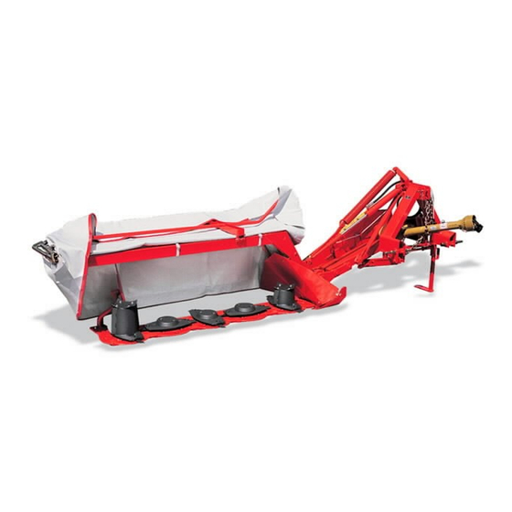
KUHN GMD24 Original Instructions Manual
Disc mower
Hide thumbs
1
2
3
Table Of Contents
4
5
6
7
8
9
10
11
12
13
14
15
16
17
18
19
20
21
22
23
24
25
26
27
28
29
30
31
32
33
34
35
36
37
38
39
40
41
42
43
44
45
46
47
48
49
50
51
52
53
54
55
56
57
58
59
60
61
62
63
64
65
66
67
68
69
70
71
72
73
74
75
76
77
78
79
80
81
82
83
84
85
86
87
88
89
90
91
92
page
of
92
Go
/
92
Contents
Table of Contents
Troubleshooting
Bookmarks
Table of Contents
1 Dear Owner
Table of Contents
2 Contents
3 Identification of the Machine
Front View
Rear View
Identification of the Machine
Optional Equipment
4 Safety
Description of Symbols Used in this Document
Safety Instructions
Introduction
Read and Follow the Safety Instructions
Precautions to be Taken before Carrying out any Operations on the Machine
Precautions to Take before Using the Machine
Precautions When Coupling
Precautions When Driving
Hydraulic Circuit
Precautions When Driving on Public Roads
Maximum Speed
PTO Shaft
Waste Disposal
Remote Controlled Components
Safety Decals
Precautions for Maintenance and Repair Work
Projection of Stones and Foreign Objects
Precautions During Manoeuvres
Precautions for Machine Use
Precautions to Take before Using the Parking Stands
Location and Description of Safety Decals on the Machine
Location of Safety Decals
Description of Safety Decals
Road Safety Equipment and Recommendations
Likely Critical Failures
Incorrect Use of the Machine by the User
Limit State Criteria
5 Machine Specifications
Description and Glossary
Designated Use of the Machine
Technical Specifications
Designated Parameters
Required Equipment
PTO Shaft
Cutter Bar
Sound Levels
6 Putting into Service
Description of Control Elements
Coupling and Uncoupling
Description of Coupling Elements
Preparing the Tractor
Preparing the Machine
Coupling the Machine
Hydraulic Connections
Electrical Connection
Check Chain
Primary PTO Shaft
Adjusting the Machine
Uncoupling the Machine
7 Instructions for Transport
Putting the Machine into Transport Position
Conformity with the Road Regulations
Machine Transport Using Transport Means
8 Instructions for Work
Putting the Machine into Work Position
Adjustments in Working Position
Cutting Height
Outer Swath Disc
Machine Use
Drive Speed
9 Optional Equipment
3/8'' - 6 Spline Pto Shaft (with Free Wheel Clutch)
Female Coupler
Raised Skid Shoes
High Cone Disc Kit
Inner Swath Disc
Inner Swath Shield
Side Deflector
Side Deflector with High Cone Disk
Frame Connection Arm/Cutterbar
Lighting and Signalling
Electrical Connection
Lateral Signalling Equipment (Only for France)
Lighting and Signalling (Only for USA)
Electrical Connection
Compensating Spring
Toolbox
Wear Skids
10 Maintenance and Storage
Frequency Chart
Lubrication
PTO Shafts
Draining
Maintenance
Belt Tension
Breather Plug Checking and Cleaning
Checking Cutterbar Oil Level
Inspection of Knives and Securing Elements
Knife Replacement
Disc Replacement
Outer and Inner Cones
Storage
At the End of each Season
At the Start of each Season
Storage
Dismantling and Scrapping of the Machine
11 Troubleshooting Guide
12 Appendix
Calculating the Load on an Axle
13 Limited Warranty
Advertisement
Quick Links
1
Lubrication
2
Checking Cutterbar Oil Level
Download this manual
Operator's manual
KN226BGB_A
Read carefully before starting the machine
Disc mower
Original instructions
KN226BGB_A
- English - 07-2019
Table of
Contents
Previous
Page
Next
Page
1
2
3
4
5
Advertisement
Table of Contents
Need help?
Do you have a question about the GMD24 and is the answer not in the manual?
Ask a question
Questions and answers
Related Manuals for KUHN GMD24
Farm Equipment KUHN GMD20 Operator's Manual
Disc mower (100 pages)
Farm Equipment KUHN GMD28 Original Instructions Manual
Disc mower (92 pages)
Farm Equipment KUHN GMD28 HD Original Instructions Manual
Disc mower (92 pages)
Farm Equipment KUHN GMD240 Operator's Manual
Disc mower (116 pages)
Farm Equipment KUHN GMD280 Operator's Manual
Disc mower (116 pages)
Farm Equipment KUHN GMD2810-FF Operator's Manual
Disc mower (92 pages)
Farm Equipment KUHN GMD 700 G II Assembly & Operators Manual
Multidisc mower (48 pages)
Farm Equipment KUHN GMD 33 N Assembly & Operators Manual
Multidisc mower (36 pages)
Farm Equipment KUHN GMD33N Operator's Manual
Disc mower (72 pages)
Farm Equipment KUHN GMD16 Operator's Manual
Disc mower (100 pages)
Farm Equipment KUHN GMD44 Operator's Manual
(95 pages)
Farm Equipment KUHN GMD 44 Assembly & Operators Manual
Select multidisc mower (45 pages)
Farm Equipment KUHN GMD702F Operator's Manual
Disc mower (72 pages)
Farm Equipment KUHN GMD 3150 TL CE Operator's Manual
Disc mower (68 pages)
Farm Equipment KUHN GMD3510-FF Operator's Manual
Disc mower (92 pages)
Farm Equipment KUHN GMD602 GII Operator's Manual
Disc mower (64 pages)
This manual is also suitable for:
Gmd24 hd
Gmd28
Gmd28 hd
Table of Contents
Save PDF
Print
Rename the bookmark
Delete bookmark?
Delete from my manuals?
Login
Sign In
OR
Sign in with Facebook
Sign in with Google
Upload manual
Upload from disk
Upload from URL


Need help?
Do you have a question about the GMD24 and is the answer not in the manual?
Questions and answers