Table of Contents
Advertisement
Advertisement
Table of Contents

Related Manuals for KUHN GF 5001 MH


Summary of Contents for KUHN GF 5001 MH
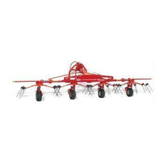
- Page 1 ASSEMBLY / OPERATOR'S MANUAL GF 5001 MH - GYROTEDDER N° 95204 C.GB - 06.2004...
- Page 2 DEAR OWNER, In buying a KUHN machine you have chosen wisely. Into it have gone years of thought, research and improvements. You will find, as have thousands of owners all over the world, that you have the best that engineering skill and actual field testing can produce. You have purchased a dependable machine, but only by proper care and operation can you expect to receive the performance and long service built into it.
-
Page 3: Table Of Contents
CONTENTS Page Safety Safety decals Technical specifications Assembly instructions Attachment : - to the tractor - PTO shaft Working position and adjustments Operating speed Transport position Parking the machine Lubrication Optional equipment Conditions of limited warranty - 1 -... -
Page 4: Safety
DESIGNATED USE OF THE MACHINE The GF 5001 MH Gyrotedder must only be used for the work for which it has been designed : spreading and turning straw and pre-mowed fodder. When fitted with a reduction gearbox, the machine can also be used for forming small night swath in order to reduce the amount of humidity getting into the crop over night. - Page 5 GENERAL SAFETY RECOMMENDATIONS Before operating the machine, always ensure that tractor and machine are in accordance with work safety and road traffic regulations. BASIC PRINCIPLES 1. In addition to the recomendations given in this manual, legislation on work safety and accident prevention must also be respected.
- Page 6 17. Never leave the tractor seat while the machine is operating. 18. Drive speed must be adapted to ground conditions as well as to roads and paths. Always avoid abrupt changes of direction. 19. Precision steering, tractor adherence, road holding and efficient braking are influenced by the type of implement, weight, ballast of front axle, ground or road conditions.
- Page 7 POWER TAKE-OFF 1. Use only the PTO shaft supplied with the machine or recommended by the manufacturer. 2. PTO guards must always be in place and in good condition. 3. Check for correct PTO overlap when at work and in transport. 4.
- Page 8 HYDRAULIC SYSTEM 1. Beware ! The hydraulic circuit is under pressure (maximum working pressure : 200 bars/2900 psi). 2. When fitting hydraulic motors or cylinders, ensure that connections have been made correctly, as per manufacturer’s instructions. 3. Before connecting hoses to the tractor hydraulics, ensure that tractor and machine circuits are not under pressure.
- Page 9 8. Spare parts used must be in accordance with specifications and standards as defined by the manufacturer. Use only genuine KUHN parts ! 9. Before any electric welding is carried out on tractor or attached machine, disconnect generator and battery terminals.
- Page 10 SPECIAL SAFETY RECOMMENDATIONS When changing the machine over from the work to the transport position or vice versa, danger of crushing and shearing can exist. Be especially careful and keep all persons away from vicinity of the machine when maneuvering. - 8 -...
-
Page 11: Safety Decals
SAFETY DECALS THE FOLLOWING SAFETY PICTORIALS HAVE BEEN PLACED ON YOUR MACHINE IN THE AREAS INDICATED. THEY ARE INTENDED FOR YOUR PERSONAL SAFETY AND FOR THE SAFETY OF THE PEOPLE WORKING WITH YOU. THE TEXT SHOWN ON THEM GIVES THEIR PRECISE MEANING. ENSURE THAT THESE PICTORIALS ARE ALWAYS LEGIBLE. - Page 12 - 10 -...
-
Page 13: Technical Specifications
TECHNICAL SPECIFICATIONS Number of rotors Working width (Din. 11220) 5.00 m / 16' 7" Width in working position 5.43 m / 17' 9" Transport width 2.84 m / 9' 2" Length in transport position 2.31 m / 7' 7" Length in working position 2.31 m / 7' 7"... -
Page 14: Assembly Instructions
ASSEMBLY INSTRUCTIONS 1) Fitting of the outer wings and cylinders (photo 1) Make sure not to invert left and right wings. Grease Digidrive coupling fingers. Connect cylinder barrels (V) to axles (A) using roll pins (C) (8x40) and plain washers (B) (21x33x4). Insert hinges (M) in housings (N) respecting the rotor timing thanks to O- rings (Q) placed on the Digidrive coupling fingers. - Page 15 3) Fitting the 3-point frame (fig. 3) Attach the 3-point frame (C) to the connecting frame (P) by means of the vertical pivot pin (A) and secure in place with roll pins (E) (5 x 50 mm) and (E’) (8 x 50 mm) as shown in figure 3. Attach the pendulum arm (B) to the 3-point frame (C) by means of the horizontal pivot pin (F).Secure the horizontal pin (F) with roll pins (G) (8 x 50 mm).
- Page 16 6) Fitting reflectors (fig. 5) Attach reflector support (1) to central tubing (2) on each side of the machine by means of 1 hexagon screw (3) (M 12 x 40), 1 self-locking screw (5) (M 12 x 40) and 1 spacer (7), as shown in fig. 5. Next stick red reflectors (8) and white reflectors (9) to the end of supports (1).
- Page 17 9) Fitting control cords (photo 9) Cut one of the cords (D 1) to 1,7 m (5' 7"). Thread it through plate (P) as shown in drawing below. Thread each end of the cord through lock arm (V) and tie a knot at each end. Insert the other cord (D 2) through the upper hole of support plate (C) then through plate (P) and tie a knot.
- Page 18 10) Fitting the safety guards (photos 10 and 10 A) The safety guards are provided with the machine to give improved protection against possible accidents and therefore ensure maximum safety. Fit both guards (6) onto support (7) and secure them with 4 hexagon bolts (8) (M 10 x 50) and nuts (M 10) (photo 10).
-
Page 19: Attachment : - To The Tractor
FITTING TO THE TRACTOR The GF 5001 MH can be fitted to all tractors equipped with a DIN or ASEA Standard 3-point linkage. The lower link pins are 22 mm and 28 mm diameter for tractors with Cat. I and II linkage. The lower link pins should be attached to the tractor link arms (P) inside the 3-point frame for Cat. -
Page 20: Pto Shaft
PTO SHAFT Connect the PTO shaft to the 540 rpm (min ) tractor drive (with the safety clutch fitted on the machine side) (photo 11). Make sure PTO length is correct : 1) When the PTO is in its maximum extended position, a minimum tube overlap of 300 mm (12") must be maintained. 2) When the PTO is in its maximum overlap position (retracted), tubes should not butt against the yokes. -
Page 21: Working Position And Adjustments
WORKING POSITION AND ADJUSTMENTS To change the machine from the transport position to the work position, proceed as follows : - Lower the machine on the ground, - Unlock pendulum arm, - Free the outside rotors by releasing locks (L). Next turn these rotors 180°... - Page 22 Hole (N) corresponds to the regular work position (photo 21). Wheels are locked in the selected position by means of locks (P) (photo 21). Positions (U) and (V) are never used on the GF 5001 MH (photo 21). If at the field ends the tractor does not lift the machine high enough to clear the outside rotors from the ground, it is possible to lift the rotors slightly using the hydraulic cylinders (see photo below).Do not forget to put again the...
-
Page 23: Operating Speed
OPERATING SPEED Many factors govern the choice of the correct forward speed : 1) The moisture content (this factor is most important the first time over). 2) The density of the crop. 3) The height and type of crop. Here are a few examples of correct speed given a crop of average length and density : - First time over : when the crop has a high moisture content, the speed is approximately 7 - 8 km/hr (4 1/2 - 5 mph) - Second time over : the speed can reach 10-12 km/hr (6 1/2 - 7 mph) according to the moisture content. -
Page 24: Transport Position
TRANSPORT POSITION To fold the machine in transport position, proceed as follows : - Disengage the PTO. - Wait for all movement to stop. - Pull cord (C) (photo 22). - Activate the tractor hydraulics and lift the outer rotors until locks (R) automatically lock into the transport position (photo 22). -
Page 25: Parking The Machine
Put male coupling of the hydraulic hose (F) into its parking support (H) (photo 24). If ever the GF 5001 MH is to be parked whilst in its transport position, an area must be used where the ground is very even and level. Wedges must always be placed under the 2central wheels (photo 24). -
Page 26: Lubrication
LUBRICATION Grease the following points with SHELL Multi- Purpose grease NLGI grade 2 : - Once a day : PTO yoke bearings and drive tubes. - Once a week : The four roors (R) (photo 25), pendulum arm, vertical 3-point frame pivot pin, pins (F), fingers of DIGIDRIVE couplings (I) (photo 26), the four wheel axles (U, photo 27), the four levers (A, photo 27) and all other pivoting points of the ma-... -
Page 27: Optional Equipment
2) DUPLEX REDUCTION GEARBOX (Kit No 111 6440) A «Duplex» reduction gearbox for the GF 5001 MH can be supplied as an optional extra when using the machine for raking night swaths. With this gearbox, the high rotor speed (rotational frequency) necessary for tedding and turning is maintained and there is also a lower rotor speed (rotational frequency) for raking night swaths. - Page 28 3) SIGNALLING ELEMENTS (Kit No. 111 6680) To install the warning board / light kit, proceed as follows : - Remove rear cosmetic shield (V) and reflector supports (1) (Foto 5, page 13). - Install warning board supports (3) (fig. 31) in place of reflector supports using the original fixation hardware, then reinstall cosmetic shield (V).
- Page 29 - At the front of the machine, connect the electric harness to the hydraulic flexible tube with 3 clamp collars (C) (length 176 mm) (photo 34), - Attach support (P) of plug (O) to the 3-point pendulum arm guard with 2 hexagon screws (H) (M 6 x 30) and 2 self-locking nuts (M 6) as shown in photo 34.
- Page 30 SOUND LEVELS Sound levels given out by : GF 5001 MH Gyrotedder Sound levels have been measured in accordance with the measuring methods as defined in: EN 1553 << Agricultural machinery - Agricultural self-propelled, mounted, semi-mounted and trailed machines - Common safety requirements >>...
-
Page 31: Conditions Of Limited Warranty
1. Normal maintenance such as greasing, maintenance of oil levels, minor adjustments, etc. 2. Transportation of any kind of any KUHN product to and from the place the warranty work is performed. 3. Dealer travel time to and from the machine or to deliver and return the machine from the workshop for repair. - Page 32 Company and have no right or authority to assume any obligation on their behalf, express implied, or to bind them in any way. KUHN S.A. reserves the right to incorporate any change in design in its products without obligation to make such changes on units previously manufactured.
- Page 33 - N O T E S -...
- Page 35 This machine complies with the safety requirements of the European machinery directive. The Operator should respect all Health and Safety regulations as well as the Highway Code. For your own safety, use only genuine KUHN spare parts. The manufacturer disclaims all responsibilities due to incorrect use or non-compliance with the...
- Page 36 KUHN parts KUHN S.A. 4 Impasse des Fabriques F - 67706 SAVERNE CEDEX (FRANCE) Tél. : + 33 (0) 3 88 01 81 00 - Fax : + 33 (0) 3 88 01 81 03 www.kuhnsa.com - E-mail : info@kuhnsa.com...
Need help?
Do you have a question about the GF 5001 MH and is the answer not in the manual?
Questions and answers