
Subscribe to Our Youtube Channel
Related Manuals for WIA Weldmatic 270 CP132-2, Iss A


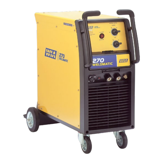
Summary of Contents for WIA Weldmatic 270 CP132-2, Iss A
- Page 1 ® Weldmatic 270 [suits W64-0 wirefeeder] Operators Manual Weldmatic 270 MIG welder Model No. CP132-2, Iss A 08/12 CP132-40 Rev D...
- Page 2 Welding Industries of Australia An ITW Company Telephone: 1300 300 884 Facsimile: 1300 301 884 Email: Info@welding.com.au www.welding.com.au...
-
Page 3: Table Of Contents
Weldmatic 270 Contents Section General Information Page Safe Practices Introduction Receiving Specifications Controls Installation Normal Welding Sequence Basic Welding Information General Maintenance External Trouble Shooting Circuit Diagram Assembly and Parts Lists Warranty information Model No CP132-2, Iss A 08/12... -
Page 4: Safe Practices
Operators Manual Safe Practices When Using Read first Welding Equipment The information contained in this These notes are provided in the interests manual is set out to enable you to of improving operator safety. They should properly maintain your new equipment be considered only as a basic guide to Safe and ensure that you obtain maximum Working Habits. -
Page 5: Fire And Explosion Prevention
Weldmatic 270 Burn Protection coating is removed from the work surface, the area is well ventilated, or the operator The welding arc is intense and visibly bright. wears an air-supplied respirator. Its radiation can damage eyes, penetrate Work in a confined space only while it is light-weight clothing, reflect from light- being ventilated and, if necessary, while coloured surfaces, and burn the skin and... - Page 6 Operators Manual A person acting as Fire Watcher must be Shock Prevention standing by with suitable fire extinguishing Exposed conductors or other bare metal equipment during and for some time after in the welding circuit, or ungrounded welding or cutting if; electrically alive equipment can fatally shock •...
-
Page 7: Introduction
Weldmatic 270 1 Introduction 2 Receiving Gas Metal Arc Welding (G.M.A.W.) is an arc Check the equipment received against the welding process where a consumable wire is shipping invoice to make sure the shipment fed by motor driven feed rolls to a welding is complete and undamaged. -
Page 8: Specifications
Operators Manual 3 Specifications Power Source Fitted Supply Cable Manufactured to Australian Standard 50/0.25 Three Core, Heavy Duty PVC AS60974-1. Cooling Primary Voltage Fan on demand, fan operates only as required to cool internal components 240 Vac, 50 Hz Insulation Rated Primary Current Class H, 140°C Rise 24.2 Amps... -
Page 9: Controls
Weldmatic 270 4 Power Source Controls Fig 1 Power Source Controls 5 Fine Voltage Control 1 Circuit Breaker This switch provides Fine adjustment of the This circuit breaker protects the 30 Vac output welding voltage over four steps. wirefeeder supply circuit. 6 Gas Outlet 2 Wirefeeder Control Socket Connector for shielding gas hose from... -
Page 10: Installation
Operators Manual 5 Installation Connection to Electrical Mains Power Successful Operation Supply Successful operation will depend on a number of factors: • Variation in circuit breaker thresholds NOTE. All electrical work shall only be undertaken by a qualified electrician. • Ambient temperature •... - Page 11 Weldmatic 270 Output Voltage Polarity To setup for this condition, connect the ‘WORK’ lead plug into the (+) output socket The design of the Weldmatic 270 allows on the Power Source, and the ‘WELDING’ selection of the output voltage polarity. lead from the wirefeeder into the (-) socket on the Power Source, as in Figure 3.
-
Page 12: Normal Welding Sequence
Operators Manual 6 Normal Welding Sequence 7 Basic Welding Information Weld Start Choice of Shielding Gas Closing the welding gun switch initiates this The choice of shielding gas is largely sequence of events: determined by the consumable wire to be used. Many proprietary shielding gas •... - Page 13 Weldmatic 270 Establishing a Weld Setting Once the consumable wire type, wire size and shielding gas have been chosen, the two variables that are adjusted in order to obtain a the desired weld setting are; • Wirefeed speed, • Welding arc voltage. The wirefeed speed determines the welding current;...
-
Page 14: General Maintenance
Operators Manual 8 General Maintenance Gun Position Before removing the power For “down hand” fillet welding, the gun is source covers, ENSURE that the normally positioned as shown in Figure 6 equipment is disconnected from below with the nozzle end pointing in the the mains power supply. -
Page 15: External Trouble Shooting
1 Power source may have overheated. to a WIA Service agent. Phone • The Weldmatic 270 welding power 1300 300 884 for details of your source incorporates an in-built over- nearest service agent. - Page 16 Operators Manual Porosity (honeycomb appearance) in Unsatisfactory Welding Performance weld and Results 1 Check the gun nozzle and gas diffuser Erratic arc characteristics caused by poor holes are free from spatter and firmly wirefeed attached to the welding gun to ensure that no air is being drawn into the Erratic wirefeed is the MOST LIKELY cause of shielded area...
-
Page 17: Circuit Diagram
Weldmatic 270 10 Circuit Diagrams - Power Source Fig 7 Power Source Circuit Diagram Model No CP132-2, Iss A 08/12... -
Page 18: Assembly And Parts Lists
Operators Manual 11.1 Assembly and Parts List - Weldmatic 270 Power Source 13 14 Fig 8 Weldmatic 270 Power Source Assembly Quality Reliability Performance • •... - Page 19 Weldmatic 270 Item # Part # Description WHL002 Wheel, Rubber, Castor PAN094 Base WHL003 Wheel, Rubber, Fixed E0053 Control Socket, 3 Pin PAN097 Side Panel E0042 Switch, Standby/Operate MR231554 Handle Left PAN096 Top Panel PAN092 Front Panel MR231553 Handle Right E0055 Switch, Coarse, 4 Position E0054...
- Page 20 Operators Manual 11.2 Assembly and Parts List - Gun and Cable Assembly Fig 9 GUN001 (200 amp) Gun and Cable Assembly Item # Part # Description BE4392 Nozzle, Brass, Tapered see ‘Tips’ page 24 Contact Tip BE4335 Gas Diffuser (Head) BE4323 BEQT2-45 Body Tube, 2”, 45...
- Page 21 Weldmatic 270 Tips Wire diameter Short series (25mm) 0.6mm BE7497 0.8mm BE7488 0.9mm BE7489 1.0mm BE7496 1.2mm BE7490 To replace liner: Disconnect gun/cable assembly at the Euro adaptor. Remove nozzle (1) and head (3). Withdraw old liner from the wirefeeder end. Insert new liner and refit gun/cable assembly to the wirefeeder.
-
Page 22: Warranty Information
Effective 1st January 2012 • The Product not having been altered, tampered with or otherwise dealt with Welding Industries of Australia (WIA) by any person in a manner other than warrants to the original retail purchaser as intended in respect of the relevant that the Weldmatic welding machine Product;... - Page 23 Weldmatic 270 Notes Model No CP132-2, Iss A 08/12...
Need help?
Do you have a question about the Weldmatic 270 CP132-2, Iss A and is the answer not in the manual?
Questions and answers