
Related Manuals for WIA WELDMATIC 270C


Summary of Contents for WIA WELDMATIC 270C
- Page 1 ® Weldmatic 270C [compact, internal wirefeeder] Operators Manual Weldmatic 270C MIG welder Model No. CP136-2, Iss A 0812 CP136-40 Rev B...
- Page 2 Welding Industries of Australia An ITW Company Telephone: 1300 300 884 Facsimile: 1300 301 884 Email: Info@welding.com.au www.welding.com.au...
-
Page 3: Table Of Contents
Weldmatic 270C Contents Section General Information Page Safe Practices Introduction Receiving Specifications Controls Installation Normal Welding Sequence Basic Welding Information General Maintenance External Trouble Shooting Circuit Diagram Assembly and Parts Lists Warranty information Model No CP136-2, Iss A 08/12... -
Page 4: Safe Practices
Recommended Shade Filter Lens Handle on Power Source Please note that the handle fitted to Pulsed Amps MMAW the Weldmatic 270C power source 0-100 12-13 is intended for manoeuvring the equipment by hand only. 100-150 12-13 150-200... -
Page 5: Fire And Explosion Prevention
Weldmatic 270C Burn Protection coating is removed from the work surface, the area is well ventilated, or the operator The welding arc is intense and visibly bright. wears an air-supplied respirator. Its radiation can damage eyes, penetrate Work in a confined space only while it is... - Page 6 Operators Manual A person acting as Fire Watcher must be Shock Prevention standing by with suitable fire extinguishing Exposed conductors or other bare metal equipment during and for some time after in the welding circuit, or ungrounded welding or cutting if; electrically alive equipment can fatally •...
-
Page 7: Introduction
• (This) Operating Manual CP136-40. steel to aluminium alloys. The Weldmatic 270C has been designed to be used with consumable wires in the range from 0.6mm to 1.2mm diameter. The smaller wire sizes are used when welding at lower currents, such as sheet-metal applications. -
Page 8: Specifications
Operators Manual 3 Specifications Cooling Manufactured to Australian Standard AS60974-1. Fan on demand, fan operates only as required to cool internal components Primary Voltage Insulation 240 Vac, 50 Hz Class H, 140°C Rise Rated Primary Current Wirefeeder Circuit Breaker Rating 24.2 Amps 5 Amps Maximum Primary Current... -
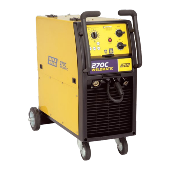
Page 9: Controls
Weldmatic 270C 4 Controls not shown Fig 1 Controls 1 Power on Indicator 3 Arc start This indicator is illuminated when the power This control can be set to modify arc starting source is switched on. conditions. For many applications the control can be set at the mid point. - Page 10 Operators Manual 4 Wire Speed Control 8 Latch Select Button and Indicator This control sets the speed of the wire drive Press to select and deselect ‘Latch’ mode. motor within the range of 0 - 172 RPM, When ‘Latch’ mode is selected, the operator equivalent to 0 - 20 metres per minute of need close the gun switch momentarily welding electrode wire.
-
Page 11: Installation
Wirefeeder Controls on Inside Panel Supply NOTE. All electrical work shall only be undertaken by a qualified electrician. The Weldmatic 270C is factory fitted with a 3 metre, 3 core 2.5 mm Heavy Duty PVC mains power supply cable with moulded 3 pin, 15 Amp, Single Phase plug. - Page 12 Operators Manual Successful Operation Output Voltage Polarity Successful operation will depend on a The design of the Weldmatic 270C allows number of factors: selection of the output voltage polarity. • Variation in circuit breaker thresholds Positive Wire • Ambient temperature G.M.A.W.
- Page 13 Fitting the gas cylinder mild steel, we recommend quality Place the gas cylinder on the tray at the rear WIA AUSTMIG ES6. Dirty, rusty or of the welder. Retain the cylinder with the kinked wire will not feed smoothly chain provided.
-
Page 14: Normal Welding Sequence
Operators Manual 6 Normal Welding Sequence Weld Start Feeding the Consumable Wire Closing the welding gun switch initiates this At the wirefeeder, release the compression sequence of events: screw and rotate the top roller arms to the open position. The end of the welding •... -
Page 15: Basic Welding Information
The recommended shielding gases for use • Wirefeed speed, with the Weldmatic 270C are: • Welding arc voltage. • Mild Steel Argon + The wirefeed speed determines the welding 5 to 25% Carbon Dioxide;... -
Page 16: General Maintenance
Operators Manual 8 General Maintenance Before removing the power source covers, ENSURE that the equipment is disconnected from the mains power supply. When the equipment is energised LETHAL VOLTAGES are present on the electrical components enclosed. Fig 7 “Bad” Weld Dust A “bad”... -
Page 17: External Trouble Shooting
There is wirefeed but no output voltage when gun switch is closed: 1 Power source may have overheated. • The Weldmatic 270C welding power source incorporates an in-built over- temperature thermostat which will trip if the welding load exceeds the operating duty cycle. - Page 18 1 Check the rating of the mains supply circuit breaker. The Weldmatic 270C should Porosity (honeycomb appearance) in be supplied from a 25 Amp or larger circuit weld breaker.
-
Page 19: Circuit Diagram
Weldmatic 270C 10 Circuit Diagram - Power Source Fig 9 Power Source Circuit Diagram Model No CP136-2, Iss A 08/12... -
Page 20: Assembly And Parts Lists
Operators Manual 11.1 Assembly and Parts List - Weldmatic 270C Power Source 21 22 Fig 10 Weldmatic 270C Power Source Assembly Quality Reliability Performance • •... - Page 21 Weldmatic 270C Item # Part # Description WHL002 Wheel, Rubber, Castor PAN131 Base WHL003 Wheel, Rubber, Fixed WF001-6 Euro Surround, Plastic PAN139 Side Panel M0049 Slam Action Catch PAN135 Door M0047 Adjusting Knob, Large M0041 Hinge Set PAN134 Top / Side Panel...
- Page 22 Operators Manual 11.2 Assembly and Parts List - WF042 Wirefeed Assembly Fig 11 Wirefeed Assembly Item # Part # Description WF045 Roller Retaining Screw Feed rolls WF027 0.9 + 1.2 mm, Solid Wire (fitted) WF026 0.6 + 0.8 mm, Solid Wire WF028 1.2 + 1.6 mm, Solid Wire WF029...
- Page 23 Weldmatic 270C 11.3 Assembly and Parts List - Gun and Cable Assembly Fig 12 GUN007 (200 amp) 3.6 m Gun and Cable Assembly Item # Part # Description BE4392 Nozzle, Brass, Tapered see ‘Tips’ page 24 Contact Tip BE4335 Gas Diffuser (Head)
- Page 24 Compress Liner 20mm Cut Here Fig 13 Replacing the gun cable liner 11.4 Assembly and Parts List - Work Lead Fig 14 Work Lead supplied with Weldmatic 270C Item # Part # Description AM352 Work Lead Includes 1.1...
-
Page 25: Warranty Information
Effective 1st January 2012 • The Product not having been altered, tampered with or otherwise dealt with Welding Industries of Australia (WIA) by any person in a manner other than warrants to the original retail purchaser as intended in respect of the relevant that the Weldmatic welding machine Product;... - Page 26 Operators Manual Notes Quality Reliability Performance • •...
- Page 27 Weldmatic 270C Notes Model No CP136-2, Iss A 08/12...
Need help?
Do you have a question about the WELDMATIC 270C and is the answer not in the manual?
Questions and answers