
Related Manuals for WIA Weldmatic 256


Summary of Contents for WIA Weldmatic 256
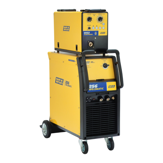
- Page 1 ® Weldmatic 256 [external wirefeeder] Operators Manual Weldmatic 256 (480 V) MIG welder With Four Roll Drive Enclosed Wirefeeder Model No. CP124-3, Iss B 05/09 CP124-41 Rev C...
- Page 2 Welding Industries of Australia An ITW Company ABN 18 004 547 111 Telephone: 1300 300 884 Facsimile: 1300 301 884 Email: Info@welding.com.au www.welding.com.au Quality Reliability Performance • •...
-
Page 3: Table Of Contents
Weldmatic 256 Contents Section General Information Page Safe Practices Introduction Receiving Specifications Controls 4.1 Power Source 4.2 Wirefeeder Installation Normal Welding Sequence Basic Welding Information General Maintenance Trouble Shooting Service Information Assembly and Parts Lists 11.1 Power Source 11.2 Wirefeeder 11.3 Wirefeed Assembly... -
Page 4: Safe Practices
Recommended Shade Filter Lens Handle on Wirefeeder Please note that the handle fitted Pulsed Amps MMAW to the Weldmatic 256 wirefeeder is 0-100 12-13 intended for carrying the equipment by hand only. 100-150 12-13 150-200... -
Page 5: Fire And Explosion Prevention
Weldmatic 256 Burn Protection coating is removed from the work surface, the area is well ventilated, or the operator The welding arc is intense and visibly bright. wears an air-supplied respirator. Its radiation can damage eyes, penetrate Work in a confined space only while it is... - Page 6 Operators Manual Walls touching combustibles on opposite Shock Prevention sides should not be welded on or cut. Walls, Exposed conductors or other bare metal ceilings, and floor near work should be in the welding circuit, or ungrounded protected by heat-resistant covers or shields. electrically alive equipment can fatally shock A person acting as Fire Watcher must be a person whose body becomes a conductor.
-
Page 7: Introduction
The CP124-3 package contains; the end of the wire, which melts into the weld pool. The arc and the weld pool are • Weldmatic 256 (480 V) Power source both shielded by gas flow from the gun, or CP124-4 in the case of “self shielded” wires, by gases •... -
Page 8: Specifications
Operators Manual 3 Specifications Power Source Wirefeeder Manufactured to Australian Standard Supply Voltage AS60974-1. 30 volts AC, (from welding power source) Primary Voltage Rated Supply Current 480 Vac, 50Hz 5 Amps Rated Primary Current Circuit Breaker 12 Amps 5 Amps Maximum Primary Current Spot Weld Time 25 Amps... -
Page 9: Power Source Controls
Weldmatic 256 4.1 Power Source Controls Fig 1 Power Source Controls 1 Circuit Breaker 4 Gas Outlet This circuit breaker protects the 30 Vac Connector for shielding gas hose from wirefeeder supply circuit. remote wirefeeder. 2 Wirefeeder Control Socket 5 Negative Welding Output Terminal Connector for control cable from remote wirefeeder. -
Page 10: Wirefeeder
Operators Manual 4.2 Wirefeeder Controls Fig 2 Controls on front face of wirefeeder 4 Wire Speed Control 1 Power On Indicator This control sets the speed of the wire drive This indicator is illuminated when wirefeeder motor within the range of 0 - 172 RPM, is connected to a power source and the equivalent to 0 - 20 metres per minute of power source is switched on. -
Page 11: Purge Button
Weldmatic 256 7 Purge Button Press to open the gas solenoid valve without energising the welding power source. 8 Inch Button Press to feed wire without energising the welding power source. The wire will feed at the current wirespeed setting. -
Page 12: Installation
G.M.A.W. with solid consumable wires is carried out with the work piece Negative and the welding wire Positive. The Weldmatic 256 (480 V) is factory fitted with a 3 metre, 3 core 30/0.25 Heavy Duty To setup for this condition, connect the PVC mains power supply cable. - Page 13 Some ‘self-shielded’ flux cored consumable The remote wirefeeder is connected to the wires are operated with the work piece Weldmatic 256 power source using 8m Positive and the consumable wire Negative. composite cable interconnecting lead. Check Refer to the manufacturers data for the all connections are firmly made to ensure good particular consumable wire to be used.
-
Page 14: Normal Welding Sequence
Operators Manual 6 Normal Welding Sequence Weld Start Check the adjustment of the spool brake, which should be set to prevent over run of Closing the welding gun switch initiates this the wire spool at the end of a weld, without sequence of events: unduly loading the wirefeed motor. -
Page 15: Basic Welding Information
The recommended shielding gases for use • Wirefeed speed, with the Weldmatic 256 are: • Welding arc voltage. • Mild Steel Argon + The wirefeed speed determines the welding 5 to 25% Carbon Dioxide;... -
Page 16: General Maintenance
Operators Manual 8 General Maintenance Before removing the power source or wirefeeder covers, ENSURE that the equipment is disconnected from the mains power supply. When the equipment is energised LETHAL VOLTAGES are present on the electrical components enclosed. Fig 7 “Good” Weld Fig 8 “Bad”... -
Page 17: Trouble Shooting
There is wirefeed but no output voltage when gun switch is closed: 1 Power source may have overheated. • The Weldmatic 256 welding power source incorporates an in-built over- temperature thermostat which will Model No CP124-3, Iss B 05/09... - Page 18 1 Check the rating of the mains supply welding arc and result in a poor weld. circuit breaker. The Weldmatic 256 should be supplied from a 25 Amp or larger circuit Porosity (honeycomb appearance) in breaker.
-
Page 19: Service Information
Weldmatic 256 10.1 Service Information - Solid State Relay Control Board CP107-10 • Welding transformer ON / OFF control in CAUTION: Mains voltage is present response to an output from the wirefeed on this control board whenever the control board (the contactor function). - Page 20 Operators Manual 10.2 Circuit Diagram - Power Source Fig 11 Power Source Circuit Diagram Quality Quality Reliability Reliability Performance Performance • • • •...
- Page 21 Weldmatic 256 10.3 Circuit Diagram - Wirefeeder Fig 12 Wirefeeder Circuit Diagram Model No CP124-3, Iss B 05/09...
-
Page 22: Power Source
Operators Manual 11.1 Assembly and Parts List - Weldmatic 256 Power Source 13 14 Fig 13 Weldmatic 256 Power Source Assembly Quality Quality Reliability Reliability Performance Performance • • • •... - Page 23 Weldmatic 256 Item # Part # Description WHL002 Wheel, Rubber, Castor PAN094 Base WHL003 Wheel, Rubber, Fixed M0020 Ratchet Cap CP107-49/1 Control Socket (6 Pin) PAN097 Side Panel PAN096 Top Panel MZ231554 Handle Left MZ231553 Handle Right E0027 Switch, Coarse, Off/1/2/3...
-
Page 24: Wirefeeder
Operators Manual 11.2 Assembly and Parts List - W60-0 Wirefeeder Fig 14 Weldmatic W60-0 Wirefeeder Assembly Quality Quality Reliability Reliability Performance Performance • • • •... - Page 25 Weldmatic 256 Item # Part # Description PAN091 Base W29-1/20 Slam Action Catch PAN087 Door W41-0/2 Hinge Set, Right Hand W41-0/1 Hinge Set, Left hand PAN088 Top / Side Panel MZ208015 Handle Assembly M0029 Adjusting Knob, Large E0016 Adjusting knob, Small...
-
Page 26: Wirefeed Assembly
Operators Manual 11.3 Assembly and Parts List - WF024 Wirefeed Assembly Fig 15 Wirefeed Assembly Item # Part # Description W26-0/13 Inlet Guide WF035 Pressure Arm, Left (complete) WF036 Pressure Arm, Right (complete) WF037 Pressure screw (complete) WF033 Rear Drive Box, Nylon WF034 Motor, 24V/50W WF032... -
Page 27: Gun And Cable Assembly
Weldmatic 256 11.4 Assembly and Parts List - Gun and Cable Assembly Fig 16 BEQ2012AO7CE (240 amp) Gun and Cable Assembly Item # Part # Description BE4392 Nozzle, brass, tapered (supplied) BE4393 Nozzle, copper, tapered see ‘Tips’ Contact Tip BE4335-116... - Page 28 Operators Manual To replace liner: Disconnect gun/cable assembly at the Euro adaptor. Remove nozzle (1) and head (3). Withdraw old liner from the wirefeeder end. Insert new liner and refit gun/cable assembly to the wirefeeder. At the gun end, compress the liner within the gun cable, then cut it one contact tip length past the end of the body tube (5).
-
Page 29: Interconnecting Lead Kit
Weldmatic 256 11.5 Assembly and Parts List - Composite Cable Interconnecting Lead Kit Fig 18 Interconnecting Lead Kit Item # Part # Description Work Lead Includes CABW25 Welding Cable 25mm WGEC4 Plug WGWC2 Work Clamp 8m Composite Cable Interconnecting Lead... -
Page 30: Warranty Information
Subject to the terms and conditions below, 2 Equipment that has been modified by any WIA warrants to its original retail purchaser that party other than WIA, or equipment that new WIA equipment sold after the effective has been improperly installed, improperly... - Page 31 WIA’s option of repair or replacement will be F. O. B. Factory at Melrose Park, Adelaide, or F. O. B. at a WIA authorised service facility as determined by WIA. Therefore no compensation or reimbursement for transportation costs of any kind will be allowed.
Need help?
Do you have a question about the Weldmatic 256 and is the answer not in the manual?
Questions and answers