
Subscribe to Our Youtube Channel
Related Manuals for WIA WELDARC 200DC


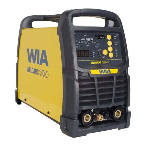
Summary of Contents for WIA WELDARC 200DC
- Page 1 Stick/TIG Welder OPERATORS MANUAL | MC113-0 From serial numbers M1132A* WELDING.COM.AU...
- Page 2 WELDING INDUSTRIES AUSTRALIA A Division of ITW Australia Pty Ltd ABN: 63 004 235 063 1300 300 884 Email: info@welding.com.au welding.com.au WELDWELL NEW ZEALAND A Division of ITW New Zealand NZBN: 9 429 039 833 129 GST NO: 080177186 0800 9353 9355 Email: info@weldwell.co.nz weldwell.co.nz...
-
Page 3: Table Of Contents
CONTENTS Section General Information Page Safe Practices Introduction Receiving Features Specifications Controls Installation Basic Welding Information General Maintenance External Trouble Shooting Trouble Shooting Chart Service Information 11.1 Circuit Diagram Assembly & Parts List Power Source Assembly & Parts List Torch Australian Warranty Information New Zealand Warranty... -
Page 4: Safe Practices
100-150 12-13 Please note that the handle fitted 150-200 10-11 11-12 12-13 to the Weldarc 200DC inverter is intended for carrying the equipment 200-300 13 12-13 12-13 by hand only. 300-400 14 DO NOT use this handle for 400-500 —... - Page 5 Burn protection that emit fumes should not be heated unless coating is removed from the work The welding arc is intense and visibly bright. surface, the area is well ventilated, or the Its radiation can damage eyes, penetrate operator wears an air-supplied respirator. light-weight clothing, reflect from light- Work in a confined space only while it is coloured surfaces, and burn the skin and...
- Page 6 Weldarc 200 DC | Operator Manual | Model No MC113-0 Walls touching combustibles on opposite Shock Prevention sides should not be welded on or cut. Walls, Exposed conductors or other bare metal ceilings, and floor near work should be in the welding circuit, or ungrounded protected by heat-resistant covers or shields.
-
Page 7: Introduction
Staincord 316L-016, Classification flux coating of the electrode. E316L-16 The Weldarc 200DC has been designed to For quality all position stainless steel be used with 2.0mm, 2.5mm, 3.2mm and 4.0mm diameter electrodes. The smaller welding. -
Page 8: Receiving
Argon flow gauge regulator REG003 If the VRD function does not suit the Gas hose application, the VRD can be enabled or disabled by an authorised WIA service agent. 3 FEATURES 3.3 Power Factor Correction (PFC) PFC provides an input power conditioner 3.1 Fan on Demand... -
Page 9: Specifications
4 SPECIFICATIONS Manufactured to Australian Standard AS60974-1 IEC60974-10 6.3.2 6.3.3. Term Value Rated Input Voltage 220 - 240 V Power Frequency 50/60 Hz Rated Input Capacity 6 KVA Generator Capacity 6 kVA Peak Rated Maximum Supply Current Imax 25 A Maximum Effective Supply Current Ieff 14 A Output No Load Voltage... - Page 10 Weldarc 200 DC | Operator Manual | Model No MC113-0 4 SPECIFICATIONS (CONT.) Term Value Cover Protection Degree IP23S Weight 12kg Shipping Weight 23kg Dimension L × W × H 500 mm x 215 mm x 345 mm Shipping Dimension L × W × H 690 mm x 320 mm x 440 mm...
-
Page 11: Controls
5 CONTROLS Power Switch Located on the rear panel Fig 1 Weldarc 200 DC Controls VRD Safe Mode Indicator Over Temperature Indicator When the machine is in MMA stick mode This light will come on if any internal thermal the light will be on when the voltage across protection devices have operated due the output terminals is reduced to safe to overheating, caused by the duty cycle... - Page 12 Weldarc 200 DC | Operator Manual | Model No MC113-0 5 CONTROLS 3 Power On 4.2 4 Step This light will be on when the input supply is In this mode the torch trigger switch turned on. is pressed to start the arc. After PRE-GAS time the Arc will initiate.
- Page 13 Adjustment Knob TIG Start Mode This knob is used to adjust welding Use This mode to select between High parameters. Frequency (HF) start, or LIFT TIG start. The knob primary function is to adjust the High Frequency (HF) arc start is welding current.
- Page 14 Weldarc 200 DC | Operator Manual | Model No MC113-0 5 CONTROLS Fig 4 Weldarc 200 DC Welding Parameters 10 Welding Parameters 10.4 Welding Current Press Adjustment Knob (5) to access The setting for actual weld current. welding parameters. 10.5 Pulse Welding 10.1 Pre Gas Pulse welding allows the current to be Pre gas flow can be set to a maximum...
- Page 15 10.5.4 Base Current 10.6 Arc Force Set the Base current Amps when in When machine is in Stick MMA mode, pulse mode. The Base Current can selecting the ARC FORCE allows be adjusted to 10 to 95% of the Peak adjustment of the increase in current Current.
- Page 16 The output current of the machine can be controlled remotely by On/ Off trigger The WIA foot control (part number switch control and current control AA76) has an in built trigger switch and adjustment, located in the torch hand current control and can be used to piece, or in foot control.
-
Page 17: Installation
Connection to Electrical Mains nnnsupply current. Power Supply Repeated Circuit breaker operation at weld The Weldarc 200DC is fitted with a 15 Amp start can sometimes be overcome by using plug, recognisable by a wide earth pin. a “D” curve circuit breaker. -
Page 18: Basic Welding Information
Select an appropriate welding current for the electrode diameter by setting the knob Connection for Stick Welding on the machine front panel. WIA AUSTARC electrodes will give the best results. It is important to select the electrode polarity in accordance with the... - Page 19 7 BASIC WELDING INFORMATION Electrode TIG TIG Welding (GTAW) Thoriated Tungsten electrodes are normally Connection for TIG Welding used for DC welding current. For TIG Welding, the TIG torch is connected Tungsten Electrode Preparation to the negative terminal. Figure 7 illustrates the correct connection of the welding torch The tungstens needs to be ground to a and gas supply.
- Page 20 Weldarc 200 DC | Operator Manual | Model No MC113-0 Tungsten Current Ranges Electrode Filler Wire Diameter (mm) Cup Size Current Amps Diameter (mm) 15-80 70-150 1.6-2.4 150-250 2.4-3.2 30° Safety Consideration Thoritated Tungsten. Thoriated Tungsten contains the 30° element Thorium (Th). Thorium is a Fig 8 Tungsten Preparation radioactive element which mainly x = 1.5 to 4 times diameter...
- Page 21 7 BASIC WELDING INFORMATION TIG Welding Operation LIFT TIG Operation Connect the Work Clamp to the work piece. When the Welding mode is set to LIFT TIG then the arc start can be achieved with the Turn on the power switch located on the rear following procedure.
-
Page 22: General Maintenance
When the equipment should be returned to a WIA is energised LETHAL VOLTAGES Service agent. Phone 1300 300 884 are present on the electrical for details of your nearest components enclosed. -
Page 23: Trouble Shooting Chart
10 TROUBLE SHOOTING CHART Problem Likely Reason Outcome All Inverter Multi-Process Models No welding current, no The machine is not turned on If confirmed that the machine display. at both the mains supply and is switched on correctly, the machine power switch. test the same outlet using a known serviceable appliance. - Page 24 Weldarc 200 DC | Operator Manual | Model No MC113-0 Problem Likely Reason Outcome MMA/STICK Models In MMAW (Stick), the arc The technique required The technique to strike is difficult to strike. for VRD enabled welding should be reviewed, not as machines is not the same as a ‘strike’...
-
Page 25: Service Information
Due to variation between M1132A......generators by different manufacturers, it is impossible for WIA to validate operation from all generators. Therefore, we recommend that CAUTION: The following information operation of equipment on the... -
Page 26: Circuit Diagram
Weldarc 200 DC | Operator Manual | Model No MC113-0 11.1 CIRCUIT DIAGRAMS – POWER SOURCE Fig 13 Weldarc 200 DC Circuit Diagram... -
Page 27: Power Source
12 ASSEMBLY & PARTS LIST - WELDARC 200DC POWER SOURCE Fig 14 Weldarc 200 DC Power Source Assembly... - Page 28 Weldarc 200 DC | Operator Manual | Model No MC113-0 WELDARC 200DC PARTS LIST Item # Part # Description M0109 Handle PAN178 Metal Cover PWA098 Emc Filter Board PWA077 IGBT Inverter Board PWA078 High Frequency Board M0110 Front Plastic Panel...
-
Page 29: Assembly & Parts List Torch
13 ASSEMBLY AND PARTS LIST – TORCH Part # Description 10N31 Collet Body 1.6mm 10N32 Collet Body 2.4mm 10N28 Collet Body 3.2mm 10N23 Collet 1.6mm 10N24 Collet 2.4mm 10N25 Collet 3.2mm 10N50 Ceramic Nozzle Size 4 (6mm) 10N49 Ceramic Nozzle Size 5 (8mm) 10N48 Ceramic Nozzle Size 6 (10mm) 10N47... -
Page 30: Australian Warranty Information
3 Year Gold Shield Warranty Statement This warranty covers the Weldarc power Effective 1st January 2022 source only, and does not extend to Welding Industries of Australia (WIA) the accessories included in the original warrants to the original retail purchaser that purchase package. - Page 31 For products purchased in Australia Our goods come with guarantees that cannot be excluded under the Australian Consumer Law. You are entitled to a replacement or refund for a major failure and for compensation for any other reasonably foreseeable loss or damage. You are also entitled to have the goods repaired or replaced if the goods fail to be of acceptable quality and the failure does...
-
Page 32: New Zealand Warranty Information
Weldarc 200 DC | Operator Manual | Model No MC113-0 15 NEW ZEALAND WARRANTY INFORMATION WIA Weldmatic MIG & Weldarc MMA Equipment 3 Year Gold Shield Warranty Statement Effective 1st January 2022 In the event of defects listed in the... - Page 33 NOTES:...
- Page 34 Weldarc 200 DC | Operator Manual | Model No MC113-0 NOTES:...
- Page 35 NOTES:...
- Page 36 WELDING INDUSTRIES WELDWELL AUSTRALIA NEW ZEALAND A Division of ITW Australia Pty Ltd A Division of ITW New Zealand ABN: 63 004 235 063 NZBN: 9 429 039 833 129 GST NO: 080 177 186 1300 300 884 Email: info@welding.com.au 0800 9353 9355 welding.com.au Email: info@weldwell.co.nz...
Need help?
Do you have a question about the WELDARC 200DC and is the answer not in the manual?
Questions and answers