Table of Contents
Advertisement
Raven
Series Fast Fiber
Advanced Media & Rate
Converters
MIL-RC3112 - 10/100BASE-TX / 100BASE-FX ST MMF
MIL-RC3113 - 10/100BASE-TX / 100BASE-FX SC MMF
MIL-RC3113-XX - 10/100BASE-TX / 100BASE-FX SC SMF
MIL-RC31W13 - 10/100BASE-TX / 100BASE-FX SC SMF TX 1310nm WDM
MIL-RC31W15 - 10/100BASE-TX / 100BASE-FX SC SMF TX 1550nm WDM
USER GUIDE
Advertisement
Table of Contents

Related Manuals for MiLAN Raven MIL-RC3112


Summary of Contents for MiLAN Raven MIL-RC3112
-
Page 1: User Guide
Raven Series Fast Fiber Advanced Media & Rate Converters MIL-RC3112 - 10/100BASE-TX / 100BASE-FX ST MMF MIL-RC3113 - 10/100BASE-TX / 100BASE-FX SC MMF MIL-RC3113-XX - 10/100BASE-TX / 100BASE-FX SC SMF MIL-RC31W13 - 10/100BASE-TX / 100BASE-FX SC SMF TX 1310nm WDM... - Page 2 - EN61000-X - Electromagnetic Immunity - EN60950 (IEC950) - Product Safety MiLAN Technology warrants to the original consumer or purchaser that each of it's products, and all components thereof, will be free from defects in material and/or workmanship for a period of five years from the original factory shipment date.
-
Page 3: Table Of Contents
Table of Contents 1. Introduction Features Package Contents 2. Hardware Description Front Panel Ports LED Indicators DIP-Switches Rear Panel 3. Installation Converter Module Rackmount Chassis Cabling 4. Troubleshooting 5. Optical Fiber Specifications 6. Technical Specifications... -
Page 4: Introduction
Introduction The Raven Series Fast Fiber Advanced Media & Rate Converters are standalone units that can be used alone or in a 10-slot rackmount chassis to connect networks with 10/100Base-TX and 100Base-FX cabling. These advanced media & rate converters extend the cabling distance of 100Base-FX network up to 2 kilometers for multi-mode fiber or 30 kilometers for single mode fiber. - Page 5 single fiber, which reduces half of the cabling cost. WDM converters must be installed in pairs with one 1310nm wavelength converter at one end of the single fiber cable and one 1550nm wavelength converter at the other end. The fiber cabling can extend the connectivity distance up to 20 kilometers.
-
Page 6: Features
Features Fast Fiber Converter Modules Comply with IEEE 802.3, 802.3u, and 802.3x standards. Convert between UTP cabling and Fiber-optic cabling. One RJ-45 connector, Auto-MDI/MDIX for UTP port. Support 10/100 Mbps Auto-negotiation for UTP port. Fiber cabling connectivity up to 30Km. Uses store-and-forward switching to separate two collision domains. - Page 7 Fiber cabling connectivity up to 20Km. Uses store-and-forward switching to separate two collision domains. 4DIP-switches to set the operation mode and Link- Loss-Forwarding function. LEDs for each port: 100, Link/Activity, Full/Collision LEDs for each unit: Power. External DC power adapter 9V/0.7A. FCC Class A, CE, UL, and CUL Mark certification...
-
Page 8: Package Contents
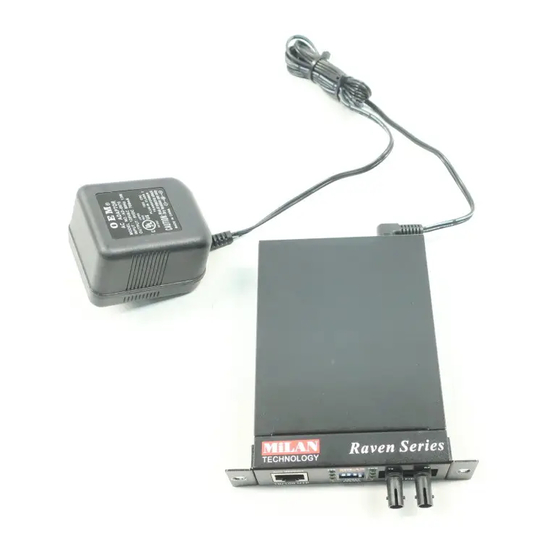
Package Contents Unpack the contents of the package and verify them against the appropriate checklist below. Fast Fiber Converter AC-DC Power Supply Users Guide Rackmount Kit Warranty Card If any item is missing or damaged, please contact your local dealer for service. -
Page 9: Hardware Description
Hardware Description Front Panel The Front Panel of the WDM Converter consists of one Single SC style single-mode connector, one RJ-45 Port (Auto MDI/MDIX), and 6 LED Indicators (UTP 100, LK/ACT, FDX/COL, Fiber LK/ACT, FDX/COL, and PWR). Figure 2-1. Front Panel for Raven Series Fast Fiber WDM Converters The Front Panel of the Fast Fiber Converter consists of one RJ-45 Port (Auto MDI/MDIX), 6 LED Indicators (UTP 100, LK/ACT, FDX, Fiber LK/ACT, FDX and PWR) and one fiber 100Base-FX Port. -
Page 10: Ports
Ports RJ-45 Port (Auto MDI/MDIX): The Ethernet RJ-45 will auto-sense for 10Base-T or 100Base-TX connections. Auto MDI/MDIX means that you can connect to another Switch or workstation without changing non-crossover or crossover cabling. Fast Fiber Port: The Fast Fiber port is for 100 Base-FX connections. -
Page 11: Led Indicators
LED Indicators There are 6 diagnostic LEDs located on the front panel of WDM Converter. They provide real-time information of system and optional status. The indicator includes Power, UTP 100, LK/ACT, FDX/COL, Fiber LK/ACT; FDX/COL. The following table provides description of the LED status and their meanings. -
Page 12: Dip-Switches
DIP-Switches The DIP-switches are used to configure operation mode for LLF (Link Loss Forwarding) and operation mode for the UTP and Fiber ports. The default value of each DIP-switch is OFF. S/W No Status Table 2-2. Fast Fiber Converter DIP-Switch statuses and meaning Link Loss Forwarding (LLF): Enabling LLF allows UTP link failures to be reported to the fiber side or Fiber link failures to be reported to the UTP side. -
Page 13: Rear Panel
Rear Panel The rear panel of the converter contains a power socket. This power socket accepts DC9V voltage and minimum 0.7A supplied current. DC IN Figure 2-3. Rear Panel for Raven Series Fast Fiber Converters... -
Page 14: Installation Converter Module
Installation Converter Module A. Remove the blank bracket by rotating thumbscrew counterclockwise. Do not discard the blank bracket. B. Open the rackmount ear kit. Each kit contains two rackmount ear pieces (with thumbscrews) and four screws. C. Attach one rackmount ear on each side of the converter using a screwdriver. -
Page 15: Rackmount Chassis
Rackmount Chassis A. Insert the modular converter module into the guides of the conversion system chassis by sliding it smoothly until it stops. Press firmly until the power plug in the chassis plugs into the modular converter module receptacle. Figure 3-2. Installing Gigabit Fiber Converter into Chassis Gently push the thumbscrews in and turn clockwise to tighten. -
Page 16: Cabling
Cabling Use four twisted-pair, Category 5 cabling for RJ-45 port connections. The cable between the converter and the link partner (switch, hub, workstation, etc.) must be less than 100 meters (328 ft.) long. Fiber segments using single-mode connector type connections must use 8/125 or 9/125 um single-mode fiber cable. -
Page 17: Troubleshooting
Troubleshooting This section is intended to help solve some common problems encountered while using the Raven Series Fast Fiber Advanced Media & Rate Converter products. Verify that the correct power adapter (DC 9V, 0.7A) is in use. Power adapters with DC output higher than 9V will seriously damage the converter modules. -
Page 18: Optical Fiber Specifications
Optical Fiber Specifications This section provides the optical fiber specifications of the Raven Series Fast Fiber Advanced Media & Rate Converter products. Module Name Modular Fast Fiber Converter (SC) Modular Fast Fiber Converter (SC-Single mode) Modular Fast Fiber Converter (ST) Modular Fast Fiber Converter (MT-RJ) Modular Fast Fiber... - Page 19 Modular Fast Fiber 12 (dBm) Converter (ST) Modular Fast Fiber 17.8 (dBm) Converter (MT-RJ) Modular Fast Fiber 17 (dBm) Converter (VF-45) Optical Specifications of Transceivers Transmitter (Output Center Wavelength): 1261~1360 nm 1310 nm Receiver (Wavelength of Operation): 1100~1600 nm Single mode Optical Transmit Power: Min.
-
Page 20: Technical Specifications
Technical Specifications This section provides the technical specifications of the Raven Series Fast Fiber Advanced Media & Rate Converter products. Standard Connector Switch architecture Fiber parameters Transparent packet IEEE802.3 10BASE-T IEEE802.3u 100BASE-TX/100BASE-FX IEEE802.3x Flow Control and Back pressure Fiber: Duplex ST/SC/MT-RJ, Simplex SC (WDM single mode) RJ-45 Socket: CAT-3/5 (10/100Mbps) Twisted Pair cable Auto MDI/MDI-X and Auto-Negotiation Function... - Page 21 Link Loss converter will force the fiber port to link down. Forward Fiber converter will force the UTP port to link down. DIP Switch 1: UTP Auto-Nego / 100Mbps Full Duplex mode DIP Switch 2: Fiber Full/Half Duplex DIP Switch DIP Switch 3: LLF (Link Loss Forwarding) Disable/Enable DIP Switch 4: Switch Converter / Pure converter...
- Page 22 90000411 Rev. B...
Need help?
Do you have a question about the Raven MIL-RC3112 and is the answer not in the manual?
Questions and answers