Sencore MRD 7000 User Manual
Receiver decoder software
Hide thumbs
Also See for MRD 7000:
- Quick start manual (3 pages) ,
- User manual (89 pages) ,
- Quick start manual (2 pages)

Related Manuals for Sencore MRD 7000


Summary of Contents for Sencore MRD 7000
- Page 1 MRD 7000 Receiver Decoder Software User Manual December 2022 8175Q www.sencore.com | 1.605.978.4600 Revision 1.15...
- Page 2 This document may also have links to third-party web pages that are beyond the control of Sencore. The presence of such links does not imply that Sencore endorses or recommends the content on those pages. Sencore acknowledges the use of third-party open-source software and licenses in some Sencore products.
- Page 3 MRD 7000 – User Manual Revision History Date (MM/DD/YYYY) Version Description Author 09/11/2017 First Draft 09/14/2017 Revisions 09/15/2017 Initial Release 11/03/2017 Feature Release 01/03/2018 Feature Release 04/20/2018 Feature Release 05/21/2019 Feature Release 10/03/2019 Feature Release 05/18/2020 Feature Release 05/27/2020 Updated Genlock Settings...
- Page 4 • Replacement Parts: When replacement parts are required, be sure the service technician uses replacement parts specified by Sencore, or parts having the same operating characteristics as the original parts. Unauthorized part substitutions made may result in fire, electric shock, or other hazards.
- Page 5 MRD 7000 – User Manual SAFETY PRECAUTIONS There is always a danger present when using electronic equipment. Unexpected high voltages can be present at unusual locations in defective equipment and signal distribution systems. Become familiar with the equipment that you are working with and observe the following safety precautions.
- Page 6 MRD 7000 – User Manual Package Contents The following is a list of the items that are included: 1. MRD 7000 Chassis 2. MRD 7000 Software 3. AC Power Cable 4. Breakout or Adapter Cables Depending on Option Modules 5. Quick Start Guide If any of these items were omitted from the packaging, please email ProCare@Sencore.com...
-
Page 7: Table Of Contents
MRD 7000 – User Manual Table of Contents SECTION 1 OVERVIEW ..........................9 ........................10 RODUCT NTRODUCTION ........................11 RONT ANEL VERVIEW ........................11 ANEL VERVIEW SECTION 2 INSTALLATION ........................15 ......................... 16 NSTALLATION AC D ..................16 EDUNDANT OWER ONNECTIONS .......................... - Page 8 3.3.4 Download SNMP MIB Files ..................... 76 3.3.5 Diagnostics..........................76 3.3.6 File Transfer Management ..................... 77 3.3.7 Updating the MRD 7000 ......................78 3.3.7.1 Applying Software Updates ......................78 3.3.7.2 Rollback Software Updates ......................81 3.3.8 Reboot Unit ..........................81 3.3.9...
-
Page 9: Section 1 Overview
MRD 7000 – User Manual Section 1 Overview Introduction This section includes the following topics: ........................10 RODUCT NTRODUCTION ........................11 RONT ANEL VERVIEW ........................11 ANEL VERVIEW Page 9 (126) -
Page 10: Product Introduction
MRD 7000 – User Manual Product Introduction The new MRD 7000 is designed to be agile, supporting new codecs and video formats through software-based updates versus traditional fixed ASIC hardware design. The MRD 7000 maintains Sencore’s long tradition of ease of use, with a straight-forward web interface accessible via all major browsers and complete control of the unit. -
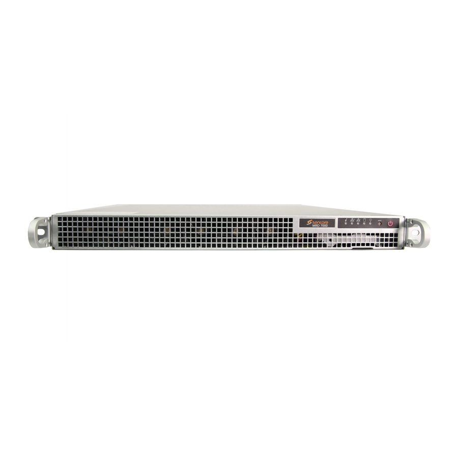
Page 11: Front Panel Overview
Redundant power design utilizing two independent cables Front Panel Overview The MRD 7000 product is a software-based solution; designed to run on a PC server chassis. Initial network configuration is done with keyboard, monitor, and mouse. Once the IP is configured all operation and setup is via web-interface over a network. - Page 12 MRD 7000 – User Manual 8. Local monitor output uses VGA (D-SUB) connector 9. Redundant power supplies (120/240 AC Switching PS) VGA and keyboard are only used for setting the network configuration; operation of the device is performed through the web interface For Single-Link SDI and HDMI 2.0 4K Playback...
- Page 13 MRD 7000 – User Manual For 12G-SDI and HDMI 2.0b Playback 1. ASI input port 1 2. SDI port 2 for 12G-SDI w/ embedded audio 3. Bi-level and tri-level genlock input port 4. Eth0: One of two available RJ45 Ethernet ports for management or MPEG/IP 5.
- Page 14 MRD 7000 – User Manual For Decoding 4xASI Input 1. 4x ASI input ports. ASI ports labeled 1 through 4 2. Local monitor output uses VGA (D-SUB) connector 3. Eth0: One of two available RJ45 Ethernet Ports for management of MPEG/IP 4.
-
Page 15: Section 2 Installation
MRD 7000 – User Manual Section 2 Installation Introduction This section includes the following topics: ......................... 16 NSTALLATION AC D ..................16 EDUNDANT OWER ONNECTIONS ..........................16 AINTENANCE KVM ....................... 17 ETWORK ETUP VIA Page 15 (126) -
Page 16: Rack Installation
Locate a protected outlet (usually inside of the rack) to plug the male ends of the power cables into. Maintenance Refer to the server manufacturer documentation for detailed information regarding server hardware maintenance. To request a copy of the latest MRD software or release notes from Sencore email ProCare@Sencore.com Page 16 (126) -
Page 17: Network Setup Via Kvm
The VGA will display the current ethernet settings and provide a text-based menu to configure IP addressing, Subnet Mask, Gateway, and DNS settings. Sencore recommends configuring the Eth0 port (Leftmost NIC when facing the rear of the unit) be set to a static IP for web-interface access. Ensure the user machine is also on the same network. -
Page 18: Section 3 Web-Interface Operation
MRD 7000 – User Manual Section 3 We b-Interface Operation Introduction This section includes the following topics: MRD 7000 W ....................19 NTERFACE VERVIEW ..........................21 ECODER ANEL ..........................73 DMIN ANEL ......................... 101 EPORTING ANEL ..........................104 BOUT ANEL... -
Page 19: Mrd 7000 Web Interface Overview
Username: admin Password: mpeg101 3.1.2 Hiding Unused Inputs The MRD 7000 web interface allows the user to hide inactive inputs using the button or show all available inputs by click the button. Only the selected input will be displayed when unused inputs are hidden. -
Page 20: Buttons And Status Indicators
To minimize the status windows again click icon. Status in the MRD 7000 web interface is shown with LED status indicators: Status is good. No errors are present, and function is Green LED operating normally. -
Page 21: Decoder Panel
MRD 7000 – User Manual Decoder Panel The Decoder panel of the MRD 7000 web interface is used to configure the unit to decode and select the desired output format to use. Each functional piece has a heading: Inputs, Conditional Access, Transport Stream Processing, Decoding, Baseband Processing, and Baseband Output sections are listed from the top down. - Page 22 MRD 7000 – User Manual Each Satellite Input and ASI Input will follow the physical ports which the name displays in the Web GUI Input File can play a stored .TS or. TRP transport stream file by uploading to the MRD 7000 internal storage.
- Page 23 The user must manually TS Sync Loss switch inputs. Decode Failure TS Sync Loss: the MRD 7000 will switch from the primary to the backup input if the primary stream loses synchronization for the duration of the Switchover Interval.
-
Page 24: Configuring Mpeg/Ip Inputs
MRD 7000 – User Manual Switchover 1-20 seconds The time in seconds which Switch On or Restore On value must remain in the configured state before the MRD 7000 switches between the Primary Input and Backup Input or vice versa. 3.2.1.1 Configuring MPEG/IP Inputs When either MPEG/IP streams are selected as the active input click on the IP address and gear icon should be visible. - Page 25 This is the only setting required to receive a unicast stream. Disabled Enabling FEC (Forward Error Correction) Enabled tells the MRD 7000 to look at Destination Port +2 and Destination Port +4 for a SMPTE 2022 FEC Matrix. IGMP Filter Mode Exclude Used on networks supporting IGMPv3.
- Page 26 MRD 7000 – User Manual The MRD 7000 can also display the individual Program/Service numbers by clicking on the Table Viewer hyperlink. Page 26 (126)
-
Page 27: Configuring File Input
MRD 7000 – User Manual 3.2.1.2 Configuring File Input When File Input is selected as the active input, clicking on the gear icon allows the user to choose source file. After Input File has been chosen, user has a possibility to: •... - Page 28 MRD 7000 – User Manual Once the File Input is played out the indicator light on the right will turn green, and the progress bar will be activated Page 28 (126)
- Page 29 MRD 7000 – User Manual The MRD 7000 can also display the individual Program/Service numbers by clicking on the Table Viewer hyperlink. Page 29 (126)
-
Page 30: Configuring Asi Input
MRD 7000 – User Manual 3.2.1.3 Configuring ASI Input When ASI Input is selected as the active input, clicking on the gear icon allows the user to enable/disable ASI ports. Once the MRD is locked on ASI signal the indicator light on the right will turn green, and the received bitrate is displayed. - Page 31 MRD 7000 – User Manual The MRD 7000 can also display the individual Program/Service numbers by clicking on the Table Viewer hyperlink. Page 31 (126)
-
Page 32: Configuring Srt Input
MRD 7000 – User Manual 3.2.1.4 Configuring SRT Input When SRT Input is selected as the active input, clicking on the gear icon allows the user to configure SRT dialog. Setting Range Description Receive Enabled This setting allows the user to enable or disable these input stream settings. - Page 33 MRD 7000 – User Manual Local Port Mode Auto, Manual In Auto Mode the local port number will be assigned In Manual Mode the local port number will be defined by the user 1 – 65535 Local Port Defines the local port number 1 –...
- Page 34 MRD 7000 – User Manual The MRD 7000 can also display the individual Program/Service numbers by clicking on the Table Viewer hyperlink. Page 34 (126)
-
Page 35: Configuring Rtp Seamless Input (Smpte 2022-7)
Used to increase or decrease the buffer Size (ms): time between path 1 & 2. Changing the size of this buffer will change how much time the MRD 7000 will buffer between the early arriving path and the late arriving path. Path 1 & 2 Setting... - Page 36 MRD 7000 – User Manual Destination Port 0 - 65535 This is the UDP port the source device is receiving from. Used on networks supporting IGMPv3. If IGMP Filter Mode Exclude this setting is set to Exclude any streams Include originating from the user defined IP addresses will be rejected.
- Page 37 MRD 7000 – User Manual The MRD 7000 can also display the individual Program/Service numbers by clicking on the Table Viewer hyperlink. Page 37 (126)
-
Page 38: Configuring Zixi Input
MRD 7000 – User Manual 3.2.1.6 Configuring Zixi Input When Zixi Input is selected as the active input, clicking on the gear icon allows the user to configure Zixi dialog. Setting Range Description Receive Enabled Enable/Disable the Zixi Input Disabled... - Page 39 MRD 7000 – User Manual 30 – 10000 ms Maximum Latency Maximum latency or buffer size in milliseconds Decryption Mode Disabled Select the type of Decryption Mode AES-128 AES-192 AES-256 Automatic Decryption Key User entry Provides the key to allow signal processing if decryption is to be done.
- Page 40 MRD 7000 – User Manual The MRD 7000 can also display the individual Program/Service numbers by clicking on the Table Viewer hyperlink. Page 40 (126)
-
Page 41: Configuring Satellite Input
MRD 7000 – User Manual 3.2.1.7 Configuring Satellite Input Only available when the MRD 70191 Satellite Input Module is installed. When Satellite Input is selected as the active input, clicking on the gear icon allows the user to enable/disable Satellite ports. - Page 42 MRD 7000 – User Manual The MRD 7000 can also display the individual Program/Service numbers by clicking on the Table Viewer hyperlink. Page 42 (126)
-
Page 43: Configuring Rtmp Input
MRD 7000 – User Manual 3.2.1.8 Configuring RTMP Input When RTMP Input is selected as the active input, clicking on the gear icon allows the user to configure RTMP Input using the pop-up configuration box. Setting Range Description Receive Enabled... - Page 44 MRD 7000 – User Manual The MRD 7000 can also display the individual Program/Service numbers by clicking on the Table Viewer hyperlink. Page 44 (126)
-
Page 45: Configuring Hls Input
MRD 7000 – User Manual 3.2.1.9 Configuring HLS Input When HLS Input is selected as the active input, clicking on the gear icon allows the user to configure HLS Input using the pop-up configuration box. Setting Range Description Receive Enabled This setting allows the user to enable or disable these input stream settings. - Page 46 The Encryption Mode is shown under Status. Configurations are displayed representing the Profile and Discovery Timeout. The MRD 7000 can also display the individual Program/Service numbers by clicking on the Table Viewer hyperlink. Page 46 (126)
-
Page 47: Configuring Conditional Access
MRD 7000 – User Manual 3.2.2 Configuring Conditional Access This section will describe how to configure descrambling in the MRD 7000. The MRD 7000 allows descambling of BISS1 and BISS2. 3.2.2.1 BISS1 Descrambling This menu allows the user to configure BISS descrambling. 12 unique BISS keys can be entered. -
Page 48: Biss2 Descrambling
MRD 7000 – User Manual Mode E Injected If Mode E is selected the user enters the BISS injected ID here. 3.2.2.2 BISS2 Descrambling This menu allows the user to configure BISS descrambling. 12 unique BISS keys can be entered. Clicking on the gear icon allows the user to configure BISS2. -
Page 49: Configuring Transport Stream Processing
The supported file types are .txt or .priv 3.2.3 Configuring Transport Stream Processing Setting Heartbeat timeout will determine the time in minutes between SCTE35 messages before the MRD 7000 will report an error. Timeout can be configured in the following way: Page 49 (126) -
Page 50: Configuring Decoding And Service Selection
MRD 7000 – User Manual 3.2.4 Configuring Decoding and Service Selection This menu allows the user to configure which service the MRD 7000 will decode. There are two editable fields in this menu. Setting Range Description Mode Auto Seek The MRD will decode the first service found... -
Page 51: Advanced Configuration
This section allows the user to configure advanced settings of the MRD 7000. Parallel Frame Processing allows the user to tune the decode latency of the MRD 7000. Lower Parallel Frames results in lower latency. Setting these values too low can result in dropped video frames. -
Page 52: Configuring Baseband Processing
MRD 7000 – User Manual 3.2.5 Configuring Baseband Processing The section of the main tab allows the user to configure the video, audio, and genlock baseband processing. 3.2.5.1 Configuring Video Baseband Processing The Configure Video menu is opened by clicking on the gear icon just under the Baseband Processing section title. - Page 53 MRD 7000 – User Manual Manual Format 3840x2160p 60fps Refer to Specification for complete list 1280x720p 59.94fps Raster Mode Solid Color Selected color outputs if no input is locked Last Frame Last decoded frame is shown when no input Raster Color...
- Page 54 MRD 7000 – User Manual Setting Range Description Overlay Type None Select subtitle overlay type Teletext Subtitles DVB Subtitles Closed Caption Teletext Subtitles 100 to 8FF Select Teletext page for Overlay DVB Subtitles Language Codes Select Subtitles for Overlay Closed Caption...
-
Page 55: Configuring Audio Baseband Processing
Configuring Audio Baseband Processing The audio menu allows the user to configure the audio processing mode (decode / discrete) settings of the MRD 7000. Up to 8 audio PID’s inside of the decoded service can be processed. The configured settings are displayed when expanding the audio status by clicking the + button. - Page 56 MRD 7000 – User Manual Setting Range Description Operational Mode Line Mode This setting allows the user to select the audio compression Monitor mode RF Mode Custom 1 Custom 0 Processing Mode Downmix Refer to Configuring SDI Audio Section 0...
-
Page 57: Configuring Genlock Processing
3.2.6.1 Configuring SDI Video The MRD 7000 comes with the ability to decode SDI Level A or SDI Level B, to disable the SDI in an error state, and to set the Quad link mode. The MRD 70140 and MRD 70141 are the two output cards that support SDI disabling. - Page 58 Description Video Loss Mode Disable SDI Setting to Disable SDI disables the SDI output of the MRD 7000 in case of an error Display Raster state. Setting to Display Raster the MRD 7000 will display the raster color selected in Section 3.2.5.1...
-
Page 59: Configuring Sdi Audio
MRD 7000 – User Manual SMPTE Standard: SMPTE ST 425-1 SMPTE ST 425-1: The Quad Link SDI output will follow SMPTE ST 425-1 SMPTE ST 425-5 mapping. This mapping format is generally designated as legacy formatting. SMPTE ST 425-5: The Quad Link SDI output will follow SMPTE ST 425-5 mapping. - Page 60 MRD 7000 – User Manual Advanced Audio embedding allows to embed mono audio channels from multiple audio PIDs in the same group/pair, i.e., a user can use mono audio left from audio PID 1 and mono audio right from audio PID 2 and embed them as Group 1 Pair 1.
- Page 61 MRD 7000 – User Manual Page 61 (126)
-
Page 62: Configuring Sdi Anc
MRD 7000 – User Manual 3.2.6.3 Configuring SDI ANC The Configure SDI menu also allows for the ability to enable or disable ANC data. Setting Range Description SMPTE2108 Enabled This setting enabled SMPTE 2038 embedding on a selected line. Disabled... - Page 63 MRD 7000 – User Manual SMPTE 2108 VANC Embedding The MRD 7000 supports extraction of SMPTE 2108 metadata from the input video PID and embedding in SDI. User configuration is needed for enabling SMPTE 2038 data to be embedded in SDI. Presence of the incoming SMPTE 2108 data is reported in the Additional Data status in the Decoding section (Transfer Characteristics).
-
Page 64: Configuring Smpte 2110 Path 1 And Path 2
3.2.6.4 Configuring SMPTE 2110 Path 1 and Path 2 This menu allows the user to configure the SMPTE 2110 output settings. The MRD 7000 comes with the ability to configure two separate paths for SMPTE 2110. Also, with SMPTE 2110 is the ability to configure eight audio pairs. Video, Audio 1-8, and Data Streams are all configurable to enable or disable the output, set Destination IP, and Destination Port. - Page 65 MRD 7000 – User Manual Setting Range Description Audio Level A The user may select the desired audio Conformance conformance level for the 2110 output. Level B Level Level A conformance consists of 1 to 8 Level C audio channels with a packet time of 1 ms Level B conformance consists of 1 to 8 audio channels with a packet time of 125 μs...
-
Page 66: Configuring Smpte 2110 Video
Display Raster IP bitrate from the 2110 card on both paths (Video, Audio and Anc). When set to Display Raster, the MRD 7000 will continue to output bitrate and the video will display the raster color selected in Section 3.2.5.1... -
Page 67: Configuring Smpte 2110 Audio
This menu allows the user to configure the SMPTE 2110 embedded audio settings. The MRD 7000 comes standard with the ability to handle up to eight audio services. Eight audio pairs can be embedded to contain a PCM (either downmixed or discrete decode). - Page 68 MRD 7000 – User Manual Setting Range Description Audio Source Silence Silence: the given audio pair on the stream will output bitrate as audio silence data. Audio 1-8 Audio 1~8: The user may select the Disabled desired audio source for each embedded audio pair.
-
Page 69: Configuring Smpte 2110 Anc
MRD 7000 – User Manual 3.2.6.7 Configuring SMPTE 2110 Anc The Configure SMPTE 2110 menu also allows for the ability to enable or disable ANC data. Setting Range Description SMPTE2108 Enabled This setting enabled SMPTE 2038 embedding on a selected line. - Page 70 Disabled SMPTE 2108 VANC Embedding The MRD 7000 supports extraction of SMPTE 2108 metadata from the input video PID and embedding in SDI/IP. User configuration is needed for enabling SMPTE 2038 data to be embedded in SDI/IP. Presence of the incoming SMPTE 2108 data is reported in the Additional Data status in the Decoding section (Transfer Characteristics).
-
Page 71: Smpte 2110 Config Overview And Sdp Download
MRD 7000 – User Manual OP47 VANC Embedding The MRD 7000 supports extraction of OP47 subtitles (UHD/HD) from the input PID and embedding in SDI/IP. User configuration is needed for enabling OP47 data to be embedded in SDI/IP. Presence of the incoming OP47 data is reported in the Additional... - Page 72 MRD 7000 – User Manual With this overview exposed, clicking the “SDP Download” icon under the SDP section on the right will download an SDP file directly to the accessing PC. While most NMOS workflows are “out-of-band”, where NMOS information is conveyed over the management network, this SDP file is for use with “in-band”...
-
Page 73: Admin Panel
MRD 7000 – User Manual Admin Panel To access the Admin Control Panel, click on the Admin tab. This menu allows the user to control many global settings and maintenance tasks on the MRD 7000. Page 73 (126) -
Page 74: Disk Usage Statistics
MRD 7000 – User Manual 3.3.1 Disk Usage Statistics The current available and used disk space of the server is shown throughout the user- interface on the top right corner of the page 3.3.2 Changing Unit Password The MRD can be assigned an access password and the current access password can be changed. -
Page 75: Profiles
MRD 7000 – User Manual 3.3.3 Profiles The MRD 7000 can save all configured settings to multiple profiles. Profiles can be saved locally, renamed, and saved to external storage to be used on other MRD 7000s. Profiles can be used to quickly and easily change the configuration of an MRD to suit different inputs and decoding requirements. -
Page 76: Download Snmp Mib Files
The MRD 7000 stores the SNMP MIB files for the currently installed version of software on the unit. These files can be downloaded directly from the MRD 7000 by clicking on button. This will open http://<IP Address>/mibs/. The browser screen below will appear where the files can be downloaded and saved from the unit. -
Page 77: File Transfer Management
The File Transfer Management configuration button opens a menu in which you can enable or disable authentication for uploading pre-recorded media files. Any changes made to the File Transfer Management will affect the FTP access and the PC File Manager access to the MRD 7000. Setting Range... -
Page 78: Updating The Mrd 7000
Applying Software Updates Once the software file is downloaded the update can be performed under the Admin tab of the MRD 7000 Web-Interface. Click on the Update Unit button in the top right of the page. The current uploaded versions are displayed in the “Software Versions” section. - Page 79 MRD 7000 – User Manual Action Button Description Upload To upload software updates to the MRD click this button. The user will be prompted to navigate to an update file. The file will then upload to the MRD. When complete the Update Unit menu will show the Update button available.
- Page 80 MRD 7000 – User Manual 4. After clicking ‘Yes’, these steps run automatically, left to right, top to bottom. Do not power cycle or otherwise interfere with the unit as it proceeds with the upgrade. The MRD will reboot after the software update is complete.
-
Page 81: Rollback Software Updates
MRD 7000 – User Manual 3.3.7.2 Rollback Software Updates The MRD stores two partitions, one with the current software and settings as well as a backup image of the last software version with settings from before the upgrade. The MRD can be reverted to that backup partition using the “Rollback” feature. -
Page 82: Unit Alias
MRD 7000 – User Manual 3.3.10 Unit Alias The Unit Alias allows a unique name or description to be entered which shows on the web-interface title pane. This is configured inside the Admin page. 3.3.11 Decoder Alias The Decoder Alias allows a unique name or description to be entered which displays under the header of the specified Decoder pane. -
Page 83: Configure Unit Networks
3.3.12 Configure Unit Networks The MRD 7000 can be assigned a Hostname and DNS servers. To access this menu, click on the Configure Networks gear icon in the Admin page. The Default Gateway of the web-interface can also be pointed at a chosen network port (Eth0 or Eth1). -
Page 84: Nmos Settings
MRD 7000 – User Manual Setting Range Description Network Name Alphanumeric, no This setting allows the user to define an optional spaces allowed unit Hostname. Mode Static IP is entered by user and will not change DHCP IP is assigned to MRD by network/router... - Page 85 MRD 7000 – User Manual Setting Range Description Physical eth0-ethX The physical ethernet port that NMOS will Connector communicate through. The maximum number of ports will depend on installed IP modules and chassis. This will need to be the same port as your Default Gateway under the Unit Network settings.
-
Page 86: Configure Smpte 2110 Video/Ip Networks
MRD 7000 – User Manual Unicast DNS Enabled Enable or Disable whether to connect to an NMOS RDS using Unicast DNS Disabled Unicast Domain The domain of the NMOS DNS. Leave blank for the system to attempt the connection as default. -
Page 87: Configuring Asi/Sdi Ports
3.3.15 Configuring ASI/SDI Ports The MRD 7000 allows users to configure the ASI/SDI ports when equipped with the MRD 70140 and MRD 70141 module. Select ASI/SDI ports 1 through 4 when Quad Link Mode is disabled to enable the ports as either SDI or ASI. A reboot must be applied for the changes to take effect. -
Page 88: Configuring Genlock
MRD 7000 – User Manual 3.3.16 Configuring Genlock SDI Output modules with the “Reference Source” configured as External must manually define the Genlock Format for the card to lock to the Genlock signal. SDI over IP (2110) modules require the “Reference Format” to always be configured to properly output video. -
Page 89: Configuring Satellite Ports
MRD 7000 – User Manual 3.3.17 Configuring Satellite Ports To make changes to lock onto the satellite signal click on the configure button next to the Satellite Module. The Satellite Module can be configured within the port menu. This allows the user to lock onto the input signal by changing the port, mode, modulation, frequency, offset, symbol rate, and scrambling code. -
Page 90: Configuring Decoder Output Modes
3.3.18 Configuring Decoder Output Modes MRD 7000 allows a user to decode single UHD or Multichannel HD/SD outputs. The two output types are SDI or SDI over IP specifically SMPTE 2110. The mode of operation for the MRD 7000 will depend on the licensing and output card installed. - Page 91 MRD 7000 – User Manual When unit completes boot up, clear the browser cache by pressing Ctrl+Shift+R to remove any front-end memory of the previous config. Verify the configuration now matches the image below. Port 1 are set to SDI, while Port 2 is set to ASI. Ports 3 and 4 will be disabled.
-
Page 92: Configuring Sdi Multichannel Decoder Outputs
MRD 7000 – User Manual 3.3.18.2 Configuring SDI Multichannel Decoder Outputs To change from Quad Link UHD or Single Port UHD mode to Multichannel mode, the user needs to select Independent (HD/SD) from the Module Configuration list. After reboot, confirm Ports 1 through 4 are set to SDI. -
Page 93: Configuring Sdi Quad Link Uhd Decode Outputs
MRD 7000 – User Manual When Independent (HD/SD) mode is successfully applied, Multichannel decoding is available via Decoder 1, Decoder 2, Decoder 3, and Decoder 4 tabs. The Summary tab displays overall status for all decoders. 3.3.18.3 Configuring SDI Quad Link UHD Decode Outputs To change from Multichannel mode or Single Port UHD mode to Quad Link UHD mode, select Quad 3G-SDI (UHD) from the Module Configuration list. - Page 94 MRD 7000 – User Manual When unit completes boot up, clear the browser cache by pressing Ctrl+Shift+R to remove any front-end memory of the previous config. Verify the configuration now matches the image below. All ports are set to SDI, and no configuration cogs present.
-
Page 95: Configuring 2110 Single Link Uhd Decode Outputs
MRD 7000 – User Manual 3.3.18.4 Configuring 2110 Single Link UHD Decode Outputs To change from Multichannel Mode to Single Link UHD mode, select 1x UHD/HD/SD from the Output Mode list. Click ‘Apply’ and then ‘Yes’ to commit the setting and reboot. -
Page 96: Configuring 2110 Multichannel Decoder Outputs
MRD 7000 – User Manual 3.3.18.5 Configuring 2110 Multichannel Decoder Outputs To change from Single Link UHD mode to Multichannel mode, the user needs to select 4 HD/SD from the Output Mode list. After reboot, confirm Decoders 1 through 4 are available. -
Page 97: Licensing
• Maintenance releases The MRD 7000 will only accept software files which were released before or during the active SSA period. Software updates released following the expiration of the SSA will be rejected on upload, until the product’s SSA has been re-activated. The actual SSA information is maintained on the product itself and can be updated by applying a license key via the web user interface. -
Page 98: Date/Time
MRD 7000 – User Manual Once the SSA period has expired, customers are free to keep using the software version they already have or other versions from before the expiration date but applying newer versions will require an extended SSA. -
Page 99: Snmp Communities
MRD 7000 – User Manual NTP Server Four decimal octets: This is the IP Address or Domain Name of the local NTP Server on the network. This setting is XXX.XXX.XXX.XXX only available if Update Mode is set to NTP. Domain Name... -
Page 100: Snmp Trap Managers
Click on the SNMP Trap Manager configuration icon to adjust the IP address of the SNMP trap destination. An example is provided below. 3.3.23 Syslog The MRD 7000 can be configured to send error and event logs formatted in the syslog protocol to a remote user specified Syslog server. Action Range... -
Page 101: Reporting Panel
MRD 7000 – User Manual Reporting Panel The Reporting tab in the MRD 7000 contains logs for active alarms currently affecting the unit and an event log. The active alarms are updated periodically to reflect the real- time state of the unit. Once an error is cleared it will be cleared from the active alarms window. -
Page 102: Event Logs
MRD 7000 – User Manual 3.4.2 Event Logs Clicking on the Logs button displays all the events and alarms that have affected the unit. If the unit is rebooted or powered off/on, the event logs are cleared. The logs can also be cleared manually by clicking the Clear button. -
Page 103: Configuring The Logs
MRD 7000 – User Manual 3.4.3 Configuring the Logs The MRD 7000 allows the user to configure alarms and events. Events and alarms can be Logged, Hidden, or have the Severity adjusted. To configure these options, click the Configure button while in the Reporting tab. -
Page 104: About Panel
MRD 7000 – User Manual Each column and its function are described below. A user configured time offset can also be applied to allow viewing the logs in a local time zone. Title Description Name This column displays the name of the error or condition. This is informational data: no options can be set here. -
Page 105: Section 4 Appendices
MRD 7000 – User Manual Section 4 Appendices Introduction This section includes the following appendices: APPENDIX A – ACRONYMS AND GLOSSARY..................106 APPENDIX B – ERROR AND EVENT LIST ....................107 APPENDIX C – SPECIFICATIONS ......................109 APPENDIX D – OPEN-SOURCE SOFTWARE .................... 123 APPENDIX E –... -
Page 106: Appendix A - Acronyms And Glossary
MRD 7000 – User Manual Appendix A – Acronyms and Glossary AAC: Advanced Audio Coding AC-3: Also known as Dolby Digital AES: Audio Engineering Society ATSC: Advanced Television Systems Committee BISS: Basic Interoperable Scrambling System Bit Rate: The rate at which the compressed bit stream is delivered from the channel to the input of a decoder. -
Page 107: Appendix B - Error And Event List
Recommended action is to set parallel frame processing to default or increase the number of frames. Firmware Unsupported The uploaded software is not supported by the MRD 7000. HLS Link Connection Error The system encountered a connection error when receiving an HLS transmission. - Page 108 MRD 7000 – User Manual SCTE 104 Line Conflict The VANC line SCTE 104 is currently set to be embedded on is conflicting with another line of data in the VANC. SCTE 104 Message The SCTE 104 message was successfully embedded into the Embedded stream.
-
Page 109: Appendix C - Specifications
MRD 7000 – User Manual Appendix C – Specifications MRD 7000 Minimum Requirements For H.264 1080P60 Decode CPU: Intel Xeon D-1520, 2.2GHz RAM: 16GB DDR4 2133MHz HDD: 256GB SSD For HEVC 4K UHD 60MB Decode CPU: Intel Xeon E-2176G, 6-core, 3.7Ghz... - Page 110 2160p x 3840 (16x9) @ 23.97, 24, 25, 29.97, 30, 50, 59.94, and 60Hz NOTE: This license adds UHD resolutions and 4x channel decoding. Some MRD 7000 output modules do not support UHD output but do support 4x HD/SD channel output.
- Page 111 MRD 7000 – User Manual AAC-LC, HE-AAC, & HE-AACv2 MPEG1L2 & MPEG2L2 SMPTE 302M Linear PCM (Pass-through) Output Formats: Digital Pass-through PCM (Decoded Discrete channels for 5.1 Sources or Downmixed for 5.1 Sources) Video Overlay Support Closed Caption Overlays: CEA-708 DVB Subtitle &...
- Page 112 Number of No limitation to the number of services descrambled per key Descrambled Services: MRD 7000 Input Features IP Input (included with MRD 7000) General – Connector: 2x 100M/1000M auto negotiate Base-T RJ-45 for MRD 70020, 70050, 70080 2x 1000M auto negotiate Base-T RJ-45 for...
- Page 113 MRD 7000 – User Manual Connector: 2x 100M/1000M auto negotiate Base-T RJ-45 for MRD 70020, 70050, 70080 2x 1000M auto negotiate Base-T RJ-45 for MRD 70081 (100M auto negotiate support with MRD 70200 installed) Receive – Protocol and IP Range:...
- Page 114 MRD 7000 – User Manual Receive – Protocol and IP Range: TCP, Unicast Payload: MP4, FLV containing H.264 and AAC or MP3 Audio Mode: Pull 0.25 – 50 Mb/s Bitrate Range: MRD 70754 - HLS Input License General – Connector:...
- Page 115 MRD 7000 – User Manual Packet Sizes 188 bytes Modes Supported: Burst, Byte and Inverted MRD 70191 - 4x DVB-S/S2 Satellite Input Module (1 slot) DVB-S/S2X tuner 4 satellite-inputs Up to 8 multi-standard demodulators F-81 Type, 75 Ohms Female (4) connectors...
- Page 116 MRD 7000 – User Manual 64APSK: 43 Msym 128APSK: 36.85 Msym 256APSK: 32.25 Msym Sensitivity (@25MSym) – QPSK 11/45: -89 dBm (20 dBµV) QPSK 1/2: -86 dBm (23 dBµV) 8PSK 9/10: -77 dBm (32 dBµV) 256APSK 3/4: -69 dBm (40 dBµV) Additional features –...
- Page 117 MRD 7000 – User Manual SMPTE 2038 SCTE 104 OP47 SMPTE 2031 VPID SMPTE 2108 Genlock Interface – Genlock Connector: 75Ω Female BNC 10kΩ Input Impedance: ≥20 dB, 0Mhz to 8 MHz Return Loss: Drive Level: 1.0 Vpp ±10% Supported Genlock References: Tri-sync and Black Burst 1080i x 1920 @ 25, 29.97 and 30fps...
- Page 118 MRD 7000 – User Manual SMPTE 2038 SCTE 104 OP47 SMPTE 2031 VPID SMPTE 2108 Genlock Interface – 75-Ω DIN 1.0/2.3 Genlock Connector: 10kΩ Input Impedance: ≥20 dB, 0 MHz to 8 MHz Return Loss: Drive Level: 1.0 Vpp ±10%...
- Page 119 MRD 7000 – User Manual Video Formats: 480i, 576i, 525i, 625i, 720p, 1080i, 1080p, 1080psf, 2160p. All common formats supported. Audio Output: Up to 8 pairs of audio streams ANC Data Support: 708 Closed Captions SMPTE 2038 SCTE 104 OP47...
- Page 120 MRD 7000 – User Manual ≥10 dB, 1.5 GHz to 3.0GHz Drive Level: 800 mVpp ±10% 12G-SDI – 12 Gb/s Data Bit Rate: 6G-SDI – 6 Gb/s 3G-SDI – 3.0 Gb/s HD-SDI – 1.5 Gb/s HDMI 2.0 Output – Digital Video Standard:...
- Page 121 MRD 7000 – User Manual Output Redundancy SMPTE 2022-7 Hitless Switching Video Standards: 8-bit and 10-bit YUV 4:2:2 SMPTE 292M, and SMPTE 425-AB Video Formats: 1080p x 1920 (16x9) @ 50, 59.94 and 60Hz NOTE: In multi-channel decoder applications, outputting more than 3x FHD streams on a 10GB link will exceed bandwidth.
- Page 122 MRD 7000 – User Manual Output Redundancy: SMPTE 2022-7 Hitless Switching Video Standards: 8-bit and 10-bit YUV 4:2:2 SMPTE 292M, and SMPTE 425-AB Video Formats: 2160p x 3840 (16x9) @ 23.97, 24, 25, 29.97, 30, 50, 59.94, and 60Hz 1080p x 1920 (16x9) @ 50, 59.94 and 60Hz 1080i x 1920 (16x9) @ 25, 29.97 and 30Hz...
-
Page 123: Appendix D - Open-Source Software
MRD 7000 – User Manual Appendix D – Open-Source Software The MRD 7000 includes: Package Version License Copyright avahi LGPL Version 2.1, February 1999 Free Software 1999 Foundation, Inc. BusyBox 1.24.2 GPL Version 2, June 1991 Erik Anderson, et. al. - Page 124 MRD 7000 – User Manual libevent 2.1.12 2007-2012 Niels Provos and Nick Mathewson Copyright (c) 1993, LIBPCAP 1.8.1 1994, 1995, 1996, 1997 The Regents of the University of California Lighttpd 1.4.30 2004, Jan Kneschke Linux 5.3.5 GPL Version 2, June 1991 Linus Torvalds, et.
- Page 125 MRD 7000 – User Manual Spawn-FCGI 1.6.3 Jan Kneschke, Stefan Bahler 2018 Haivision Systems 1.4.2 MPLv2.0 License Inc. TCLAP 1.2.0 2003 Michael E. Smoot uuid 1.0.3 Robert Boehne Zlib 1.2.7 zlib/libpng License 1995-2005 Jean-loup Gailly and Mark Adler Page 125 (126)
-
Page 126: Appendix E - Warranty
Appendix F – Support and Contact Information Returning Products for Service or Calibration The MRD 7000 server is a delicate piece of equipment and needs to be serviced and repaired by Sencore. Periodically it is necessary to return a product for repair or calibration.
Need help?
Do you have a question about the MRD 7000 and is the answer not in the manual?
Questions and answers