
Related Manuals for Sencore openGear AG 4400


Summary of Contents for Sencore openGear AG 4400
- Page 1 AG 4400 Receiver Decoder Card User Manual June 2020 8122K www.sencore.com | 1.605.978.4600 Revision 1.10...
- Page 2 This document may also have links to third-party web pages that are beyond the control of Sencore. The presence of such links does not imply that Sencore endorses or recommends the content on those pages. Sencore acknowledges the use of third-party open source software and licenses in some Sencore products.
- Page 3 AG 4400 – User Manual Revision History Date (DD/MM/YYYY) Version Description Author 11/11/2014 Initial Release (2.2.0 software) 03/30/2015 Update for 2.3.0 Release 06/16/2015 Update for 2.3.3 Release 07/20/2015 Update for 2.4.0 Release 11/01/2015 Update for 2.5.0 Release 03/02/2016 Update for 3.0.0 Release 06/06/2016 Update for 3.1.0 Release 09/28/2016...
- Page 4 Replacement Parts: When replacement parts are required, be sure the service technician uses replacement parts specified by Sencore, or parts having the same operating characteristics as the original parts. Unauthorized part substitutions made may result in fire, electric shock or other hazards.
- Page 5 Always refer to the manual for safe operation. If you have a question about the application or operation call Sencore for assistance. WARNING – To reduce the risk of fire or electrical shock never allow your equipment to be exposed to water, rain or high moisture environments.
- Page 6 AG 4400 – User Manual FCC Class A Information The AG 4400 has been tested and found to comply with the limits for a Class A digital device, pursuant to Part 15 of the FCC Rules. These limits are designed to provide reasonable protection against harmful interference when the equipment is operated in a commercial environment.
- Page 7 Note: If any option cables were ordered with the AG 4400, they will be included in the box as well. If any of these items were omitted from the packaging of the AG 4400 please call 1-800- SENCORE to obtain a replacement. Manuals for Sencore products can be downloaded at www.sencore.com 1) Declaration of Conformity...
-
Page 8: Table Of Contents
AG 4400 – User Manual Table of Contents Section 1 Overview ................... 10 Product Introduction ....................11 Cooling ........................11 Rack Information ......................11 Section 2 Getting Started ................. 12 Installation ........................13 Onboard Controls and LEDs..................13 Backplane ........................15 Maintenance ...................... - Page 9 AG 4400 – User Manual 3.3.9 Configuring SNMP ....................73 3.3.10 Syslog ........................75 3.3.11 In-Band Control ....................76 3.3.12 Updating the AG 4400 ..................76 3.3.13 Reboot Unit ......................78 3.3.14 Reset Defaults ...................... 78 Reporting Panel ......................79 3.4.1 Active Alarms ......................
-
Page 10: Section 1 Overview
AG 4400 – User Manual Section 1 Overview Introduction This section includes the following topics: Product Introduction ....................11 Cooling ........................11 Rack Information ......................11 Page 10 (106) -
Page 11: Product Introduction
AG 4400 is adaptable to most decoder use cases. The card also maintains Sencore’s long tradition of ease of use, with a web interface accessible via all major browsers once an IP address is assigned to the card using the openGear , and is backed by Sencore’s best-in-class ProCare support. -
Page 12: Section 2 Getting Started
AG 4400 – User Manual Section 2 Getting Started Introduction This section includes the following topics: Installation ........................13 Onboard Controls and LEDs..................13 Backplane ........................15 Maintenance ......................15 Setting up the AG 4400 using DashBoard ............. 15 Page 12 (106) -
Page 13: Installation
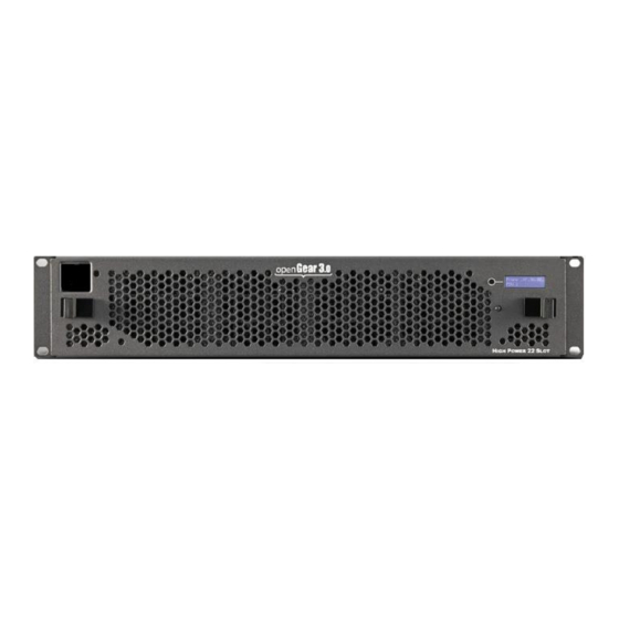
Carefully unpack the AG 4400 card and inspect it for any signs of damage. Do not insert the card into the openGear frame if any damage is evident, and if so, please contact Sencore. The AG 4400 occupies two slots in the AG-4800A openGear frame, allowing up to 10 cards to be inserted into the frame. - Page 14 AG 4400 – User Manual Figure 2: View of card edge controls and LEDs Button Controls There are two button controls available on the AG 4400: Boot to Recovery Image: If the card becomes corrupted, the user can remove the card from the slot and then reinsert the card while pressing and holding this button to boot to the recovery image.
-
Page 15: Backplane
AG 4400 – User Manual Backplane Each AG 4400 card comes paired with a compatible backplane. Figure 3 shows the backplane for an AG 4400 card with the DVB-S2 input option. Figure 3: Backplane with DVB-S2 Input Option Maintenance The AG 4400 is virtually a maintenance-free piece of equipment. There are no user serviceable parts on the card. - Page 16 Figure 4 shows the startup DashBoard screen. DashBoard has discovered an accessible frame. Note the “Sencore 4800A Frame1” icon near the top of the Basic Tree View pane. Clicking on the triangle ( ) symbol next to the frame name will display the available cards in the frame.
- Page 17 AG 4400 – User Manual Figure 5: Available cards window view Figure 5 shows that the Master Frame Controller (MFC) card, and the Sencore AG 4400 card are available in slots 0 and 3, and are currently showing no alarms. Hovering the mouse pointer over each LED icon will give a tooltip style summary of status.
- Page 18 AG 4400 – User Manual Figure 6: Configuration and Web Interface in Basic Tree View Network setup using DashBoard Double clicking “Configuration” will launch the setting and status window panes for the AG 4400 card shown in Figure 7. Figure 7: Configuration Page 18 (106)
- Page 19 AG 4400 – User Manual In the setting pane, the user can view the following network configuration settings: 1) IP Address 2) Subnet Mask 3) Default Gateway 4) Mode The AG 4400 card can be assigned either assigned an IP address either manually, or by DHCP (card will be set to DHCP by default).
-
Page 20: Section 3 Operating The Web Interface
AG 4400 – User Manual Section 3 Operating the Web Interface Introduction This section includes the following topics: AG 4400 Web Interface Overview ................21 Main Panel ......................... 23 Admin Panel ......................66 Reporting Panel ......................79 About Panel ....................... 83 Page 20 (106) -
Page 21: Ag 4400 Web Interface Overview
AG 4400 – User Manual AG 4400 Web Interface Overview 3.1.1 Logging into the AG 4400 Web Interface Once an IP address is set, each of the cards can be independently controlled via the web interface. To open the AG 4400 web interface use one of the following supported browsers and navigate to the card’s IP address: ... -
Page 22: Drag And Drop Menus
AG 4400 – User Manual When the icon is shown additional status information can be viewed. Click this button will expand the menu to display the additional status information. All text in status menus shown in ORANGE are user configurable settings. Text shown in BLUE is not user configurable and is strictly a status or value. -
Page 23: Main Panel
AG 4400 – User Manual Main Panel The Main panel of the AG 4400 web interface is used to configure the unit to decode, de-encapsulate and demodulate. When configuring the AG 4400 the user begins at the top of the menu and works down. The inputs are configured, then descrambling (if present), then service or PIDs are selected for decode, then outputs are configured. - Page 24 AG 4400 – User Manual Primary and Backup Inputs by clicking the button. To change the active input and failover settings click the icon next to Input Selection as shown in Figure 9 and Figure 10 below. Figure 9: Active Input Indicator Figure 10: Active Input and Failover Configuration Menu Setting Range...
-
Page 25: Configuring Asi Input
AG 4400 – User Manual None Switch On Manual Only Manual Only: the unit will not switch inputs automatically. The user must manually TS Sync Loss switch inputs. Decode Failure TS Sync Loss: the AG 4400 will switch from the primary to the backup input if the primary stream loses synchronization for the duration of the Switchover Interval. -
Page 26: Configuring Mpeg/Ip Input
AG 4400 – User Manual Port Enabled This setting allows the user to enable or disable the ASI Input to the AG 4400. Disabled Null Stripped Disabled Enabling Null Stripped allows the AG 4400 to receive streams that do not contain null Enabled packets. - Page 27 AG 4400 – User Manual Setting Range Description Receive Enabled This setting allows the user to enable or disable these input stream settings. Disabled Physical Port 1 The physical connector on the MPEG/IP Connector card that will be used to receive the input. Port 2 Mode Multicast setting allows the card to receive...
-
Page 28: Configuring Dvb-S/S2 Input
AG 4400 – User Manual Buffer Mode Size (KB) Allows option to set buffer mode to Size in KB or Delay ms Delay (ms) 10 – 600 KB Buffer Size (KB) This setting determines how much data is received before the AG 4400 starts decoding. - Page 29 AG 4400 – User Manual (labeled A and B) which only one port can be active at a time. This menu is for setting up the reception of DVB-S/S2 satellite signals. The menu for Port A and B have the same settings. Figure 13: DVB-S2 Configuration Menu Setting Range...
-
Page 30: Configuring 8Vsb/Qam Input
AG 4400 – User Manual LO Offset 5150 The offset in MHz that the local oscillator is operating. 9750 10600 10750 11250 Symbol Rate Manual The Manual option allows the user to Mode choose the symbol rate. The Auto option Auto automatically detects the incoming symbol rate. -
Page 31: Configuring Dvb-T2/C2/Isdb-T Input
AG 4400 – User Manual Setting Range Description Receive Enabled This setting allows the user to enable or disable this reception port. Disabled Mode 8VSB This setting allows the user to choose between 8VSB or QAM modulation 64-QAMB schemes. 256-QAMB Channel Plan Off Air If 8 VSB is the selected Mode, the only... - Page 32 AG 4400 – User Manual Setting Range Description Receive Enabled This setting allows the user to enable or disable this reception port. Disabled Mode DVB-T This setting allows the user to choose between DVB-T/T2/C/C2 or ISDB-T DVB-T2 modulation schemes. DVB-C DVB-C2 ISDB-T Channel Plan...
-
Page 33: Configuring Dvb-Ci Descrambling
AG 4400 – User Manual United Kingdom European Cable Japan Philippines Channel Select a channel from the channels available in the dropdown. The list of available channels will be based on which channel plan is selected Frequency (MHz) 42-1002 Selecting a channel from the channel dropdown will populate this field automatically based on the user selected channel. - Page 34 AG 4400 – User Manual 3.2.7.1 Configuring DVB-CI module This menu allows the user configure the DVB-CI module in the AG 4400 as shown in Figure 14. The AG 4400 has one DVB-CI slot where a CAM Module can be inserted. The CAM Module can be reset manually using the button.
-
Page 35: Configuring Biss Descrambling
AG 4400 – User Manual options are applicable only if the Mode in the DVB-CI settings is set to Selected PIDs or Selected Services (Refer to Section 3.2.7.1). The drag and drop method can be used to drag services from the right column to the left column. - Page 36 AG 4400 – User Manual 3.2.8.1 Configuring BISS Keys This menu allows the user to configure BISS descrambling, as shown in Error! Reference source not found.. 12 unique BISS keys can be entered. If the BISS mode is set to Mode E a icon will appear next to Mode E Injected ID.
- Page 37 AG 4400 – User Manual Selected Key Key 1-12 Select a Key to configure Alias 16 characters Set an Alias for the selected key. Mode Mode 1 This setting sets the Mode of the BISS key that has scrambled the transport stream. Mode E Mode 1 Session Word If Mode 1 is selected the user enters the...
-
Page 38: Configuring Service Selection
AG 4400 – User Manual Figure 17: BISS Service Descrambling Menu 3.2.9 Configuring Service Selection This menu allows the user to configure the PIDs or Service the AG 4400 will decode. Depending on the Selection Mode that is set, the menu will change to reflect the applicable settings. - Page 39 AG 4400 – User Manual Figure 18: Service Lock Selection Menu Setting Range Description Selection Mode Service Lock Setting to Service Lock sets the card to decode any PIDs associated with a service PID Lock number or service name. Setting to PID Lock sets the card to decode only the PIDs Auto Seek specified in the PID Lock Configuration...
- Page 40 AG 4400 – User Manual Note: S302M Audio Type is now auto detected by the AG4400 PID Lock Mode In PID Lock mode the AG 4400 will only decode the PIDs specified by the user in the PID Lock Configuration matrix as shown in Figure 19. The drag and drop method can be used to auto-populate the cells in the matrix.
- Page 41 AG 4400 – User Manual Figure 20: Auto Seek Menu Page 41 (106)
-
Page 42: Configuring Video Services
AG 4400 – User Manual 3.2.10 Configuring Video Services The menu in Figure 21 allows the user to configure the SDI, Digital Video and Composite output formats of the AG 4400. Overlays and image insertion are configured in this menu as well. Figure 21: Video Configuration Menu Setting Range... - Page 43 AG 4400 – User Manual 4x3 Output Aspect Disabled If 4x3 Auto Conversion is set to Disabled Ratio Auto Conversion the AG 4400 uses the 4x3 Conversion Mode setting to format video. If 4x3 Auto Conversion is set to AFD the AG 4400 will apply the conversion defined by the AFD code in the incoming stream.
-
Page 44: Configuring Audio
AG 4400 – User Manual subtitles are displayed. Only the languages present in the stream are given. Teletext Subtitles 3 Hexadecimal If Teletext Subtitles overlays are enabled Characters this setting choosing the page (language) of which subtitles are displayed. Only the pages present in the stream are given. - Page 45 AG 4400 – User Manual Setting Range Description Operational Mode Line Mode Refer to Appendix E for explanation. RF Mode Custom 1 Custom 0 Processing Mode Downmix Appendix Refer to E for explanation. Discrete Refer to Appendix F for explanation Discrete Channels Lf/Rf Selectable Pairs of Discrete...
-
Page 46: Configuring Genlock
AG 4400 – User Manual 3.2.12 Configuring Genlock If the Genlock Reference option was selected as a factory installed option, the following menus and options in Figure 23 will be available for configuration. This menu allows the user to configure the genlock reference used by the AG 4400. The AG 4400 can be configured to use an external user provided reference or disabled completely. - Page 47 AG 4400 – User Manual application where the AG 4400 is receiving a transport stream with SCTE35 DPI splice messages. In an SCTE 35 to 104 configuration, the AG 4400 extracts SCTE 35 messages from the transport stream and converts them to SCTE104 messages, and embeds them as VANC packets on the SDI output.
- Page 48 AG 4400 – User Manual Figure 25: SCTE35/ESAM Insertion Configuration Tab Setting Range Description State Enabled Enable or Disable SCTE 35 message Insertion Disabled 0-8191 PID on which the inserted SCTE 35 messages will be inserted Splice Type Normal Selects whether the SCTE 35 message will be of the “splice immediate”...
-
Page 49: Esam
AG 4400 – User Manual Avail Num 0-255 Authentication for a specific avail in the Unique Program ID Avails Expected 0-255 Number of Avails expected in the current viewing event Messages can be manually inserted by clicking the green arrow that is shown in Figure 26 when the SCTE 35 section is expanded. - Page 50 AG 4400 – User Manual Figure 27: SCTE35/ESAM ESAM Configuration Tab Setting Range Description ESAM Processing Enabled Enable or Disable ESAM processing Disabled POIS URI Valid String Specify the address of the POIS server POIS Timeout (sec) Specify a timeout to receive a response from the POIS Timeout Behavior Pass Message...
-
Page 51: Configuring Ancillary Data Options
AG 4400 – User Manual SCTE 35 PID present PID on which the SCTE 35 messages will in TS be inserted in the transport stream 3.2.15 Configuring Ancillary Data Options The menu in Figure 28 allows the user to configure processing options relating to ancillary (ANC/VBI) data generation. -
Page 52: Configuring Sdi Outputs Port 1 & 2
AG 4400 – User Manual 3.2.16 Configuring SDI Outputs Port 1 & 2 The following menus (Figure 29 and Figure 30) allow the user to configure the embedded audio and auxiliary data in the SDI video output. There are unique settings for SD and HD video. - Page 53 AG 4400 – User Manual SD-SDI General Setting Range Description Video Loss Mode Disable SDI Setting to Disable SDI disables the SDI output of the AG 4400 in case of an error Display Raster state. Setting to Display Raster the AG 4400 will display the raster color selected in Section 3.2.10.
- Page 54 AG 4400 – User Manual SCTE104 Enabled Enable/Disable SCTE104 embedding in the VANC. Choose one line between Disabled lines 4-19 to embed data. SD-SDI VBI Embedding When the AG 4400 is configured to output SD video the VBI data can be encoded into the vertical blanking as a VBI waveform.
- Page 55 AG 4400 – User Manual Figure 30: HD-SDI Output Configuration Menu HD-SDI General Setting Range Description Video Loss Mode Disable SDI Setting to Disable SDI squelches the SDI output of the AG 4400 in case of an error Display Raster state.
- Page 56 AG 4400 – User Manual 4400 will display the raster color selected in Section 3.2.10. HD-SDI VANC Embedding Setting Range Description EIA 708-B Enabled Enable/Disable EIA 708-B Closed Caption embedding in the VANC. Disabled Choose one line between lines 4-19 to embed data.
-
Page 57: Configuring Sdi Audio Embedding
AG 4400 – User Manual 3.2.17 Configuring SDI Audio Embedding The menu in Figure 31 allows the user to configure SDI embedded audio settings. The AG 4400 comes standard with the ability to handle up to two audio services. With additional licensing the AG 4400 can handle up to four unique audio services. When licensed for four audio services the user will have four audio pairs available to embed audio in the SDI. -
Page 58: Configuring Digital Audio Output
AG 4400 – User Manual Configuring SDI Output Setting Range Description Setting Range Description Config Stereo This allows for the Group and Pair to be stereo audio or mono audio. Mono Stereo Setting Range Description Source Assigning a PCM audio to a Group Pair will embed the decoded or downmixed two channel audio Audio 1-8 PCM Section... - Page 59 AG 4400 – User Manual Configuring Digital Audio Output Setting Range Description Config Stereo This allows for the Group and Pair to be stereo audio or mono audio. Mono Stereo Setting Range Description Source Assigning a PCM audio to a Digital Output will downmix the audio to two channel audio using the Audio 1-8 PCM Section...
-
Page 60: Pid Filter
AG 4400 – User Manual or Channel 2 embed the decoded or downmixed right channel Section audio using the settings defined in 3.2.11. Selecting Disabled turns off the Group Pair completely. 3.2.19 PID Filter If the PID/Service Filter license is enabled, the following menus and options will be available for configuration. -
Page 61: Configuring Asi Output
AG 4400 – User Manual Selection Mode Use Selected Use Selected Services/PIDs will allow the user to Services/PIDs select which services are in the new TS. Use Decoded Service will only include the service that Use Decoded is currently selected for decoding by the AG 4400 Service 3.2.20 Configuring ASI Output... - Page 62 AG 4400 – User Manual Figure 33: MPEG/IP Transmit Configuration Menu Setting Range Description Transmit Enabled Enable or disable the MPEG/IP transmit group. Disabled Source Unmodified Input Unmodified Input will pass the incoming TS to the output without applying any BISS or DVB-CI Descrambled decryption.
-
Page 63: Configuring The Mpeg/Ip Mpe Outputs
AG 4400 – User Manual the address must be sent within the multicast IP range. Destination Port 0 - 65535 When sending to a unicast address, the destination port must match the receiving device’s port. When sending a multicast, any port within the accepted range can be used, but it is good practice to always choose a port >1030 and an even number... - Page 64 AG 4400 – User Manual Setting Range Description Transmit Enabled Enable or disable transmission of de-encapsulated MPE data. Disabled Physical Port 1 The physical connector on the MPEG/IP card that Connector will be used to transmit the MPE data. Port 2 Selected MPE PID from the transport stream to use for MPE output MAC Filter State...
-
Page 65: Viewing Psip Information
AG 4400 – User Manual 3.2.23 Viewing PSIP Information To view the PSIP information for the applied TS, select the View PSI Tables button located on the right hand side of the Inputs section. This will open a new window that displays all of the PSIP information for the applied TS. -
Page 66: Admin Panel
AG 4400 – User Manual Admin Panel Figure 34: Admin tab Page 66 (106) -
Page 67: Changing Unit Password
AG 4400 – User Manual To access the Admin Control Panel (Figure 34), click on the tab. This menu allows the user to control many aspects of the AG 4400. 3.3.1 Changing Unit Password The AG 4400 can be assigned an access password and the current access password can be changed. -
Page 68: Diagnostics
The AG 4400 provides the user the ability to take a snapshot of ALL current unit settings, reported values, active alarms, and the alarm and log file history. This snapshot will be downloaded as a .XML format file that can be sent to Procare at Sencore for analysis. -
Page 69: Unit Network Configuration
AG 4400 – User Manual before allowing any changes to be made. To edit the Unit Alias or protect the BISS-E Injected ID click on the button (Figure 35). The PID Display mode changes how PID values are displayed in the web interface. The values can either be displayed in decimal or HEX values. - Page 70 AG 4400 – User Manual NOTE: Exercise extreme caution when performing changes to this menu as network communication can be lost with the AG 4400. Setting Range Description Mode DHCP Setting to DHCP will allow the network assign an IP address automatically to the AG 4400 (if Static supported).
-
Page 71: Mpeg/Ip Network Configuration
AG 4400 – User Manual 3.3.6 MPEG/IP Network Configuration The MPEG/IP option is used to receive MPEG over IP transport streams. The MPEG/IP option supported unicast, multicast, UDP and RTP. The ports on the AG 4400 backplane can be configured from the web interface. To configure the Default Gateway and ICMP Response settings (Figure 37) click the button. -
Page 72: Licensing
License is Supported or Unsupported by the installed hardware If licenses need to be applied to the AG 4400 click button. The menu in Figure 39 will appear where the user can copy and paste the provided license key from Sencore. Figure 39: License Key 3.3.8 Date/Time The AG 4400 can be set to synchronize with an NTP server or a manual date and time can be defined by the user. -
Page 73: Configuring Snmp
AG 4400 – User Manual Figure 40: Date/Time Configuration Menu Setting Range Description Update Mode Setting to NTP uses the local network’s NTP server to synchronize date and time. Manual Manual allows the user to define a date and time. NTP Server Four decimal octets: This is the IP Address or Domain Name of the... - Page 74 AG 4400 – User Manual Figure 41: SNMP Community Configuration Menu 3.3.9.2 SNMP Trap Managers The SNMP trap managers are recipients of SNMP traps sent from the AG 4400. The following menu allows the user to configure the recipient’s IP addresses. To add and remove recipients of the SNMP traps click the button (Figure 42).
-
Page 75: Syslog
AG 4400 – User Manual 3.3.9.3 Download SNMP MIB Files The AG 4400 stores the SNMP MIB files for the currently installed version of software on the unit. These files can be downloaded directly from the AG 4400 by clicking on the button. -
Page 76: In-Band Control
The In-Band Control is used to change settings and receive updates from data within a PID in the incoming TS, as injected by the Sencore CMD 4000 In-band Control Server. The menu in Figure 45 allows the user to configure the In-Band Control settings. - Page 77 AG 4400 – User Manual updates to the unit click on the button. The current version and uploaded version are displayed in the Software Versions section as shown in Figure 46. The AG 4400 will reboot after a software update is complete. Figure 46: Update Unit Menu Action Button...
-
Page 78: Reboot Unit
AG 4400 – User Manual Figure 47: Rollback Unit Software Menu Action Button Description Rollback Software Clicking this button starts the Rollback process. The AG 4400 will prompt the user to confirm the rollback or click cancel to stop the process. 3.3.13 Reboot Unit The AG 4400 can be rebooted from the web interface. -
Page 79: Reporting Panel
AG 4400 – User Manual Reporting Panel Figure 48: Error Reporting Page tab in the AG 4400 contains logs for active alarms currently affecting the unit and an event log as shown in Figure 48. The active alarms are updated periodically in order to reflect the real-time state of the unit. -
Page 80: Event Logs
AG 4400 – User Manual Figure 49: Active Alarms Title Description State This column displays the nature of the alarm. The icon means the log entry is informational and is not an error. The icon means the log entry is an active alarm. Name This column displays the description of the error. -
Page 81: Configuring The Logs
AG 4400 – User Manual Figure 50: Condition and Event Log Title Description Severity This column displays the nature of the alarm. The icon means the log entry is informational and is not an error. The icon means the log entry is an active alarm. Timestamp This column displays the date and time the error was raised or cleared. - Page 82 AG 4400 – User Manual button while in the tab. The tab allows the user to configure the alarms reported by the AG 4400. The tab allows the user to configure the events reported by the AG 4400. Each column and its function are described below.
-
Page 83: About Panel
About Panel Figure 52: About tab Under the tab, there are no user definable parameters but there is information about software versions currently installed, which licenses are installed, how to contact Sencore, and third party software information. Page 83 (106) -
Page 84: Section 4 Appendices
AG 4400 – User Manual Section 4 Appendices Introduction This section includes the following appendices: – Acronyms and Glossary ............ 85 Appendix A – Error and Event List ............88 Appendix B – Specifications ..............91 Appendix C – AG 4400 Audio Explanation ..........99 Appendix D –... -
Page 85: Appendix A - Acronyms And Glossary
AG 4400 – User Manual Appendix A – Acronyms and Glossary 8VSB: Vestigial sideband modulation with 8 discrete amplitude levels. 16VSB: Vestigial sideband modulation with 16 discrete amplitude levels. AAC: Advanced Audio Coding AC-3: Also known as Dolby Digital AES: Audio Engineering Society AFD: Active Format Descriptor AG: Atlas Gear ASI: Asynchronous Serial Interface... - Page 86 AG 4400 – User Manual High level: A range of allowed picture parameters defined by the MPEG-2 video coding specification which corresponds to high definition television. I/O: Input/Output IP: Internet Protocol Kbps: 1000 bit per second LED: Light Emitting Diode LNB: Low-Noise Block MAC: Medium Access Control Main level: A range of allowed picture parameters defined by the MPEG-2 video coding...
- Page 87 AG 4400 – User Manual RPM: Revolutions Per Minute RRT: Rating Region Table RS-232: Recommended Standard. A standard for serial binary data interconnection. RU: Rack Unit RW: Read/Write SD: Standard Definition SDI: Serial Digital Interface SFP: Small Form-Factor Pluggable SI: System Information SMPTE: Society of Motion Pictures and Television Engineers SNMP: Simple Network Management Protocol SPTS: Single Program Transport Stream...
-
Page 88: Appendix B - Error And Event List
AG 4400 – User Manual Appendix B – Error and Event List Error Description 12V Supply Error Voltage on 12V rail has exceeded safe operational range. 3.3V Supply Error Voltage on 3.3V rail has exceeded safe operational range. 5V Supply Error Voltage on 5V rail has exceeded safe operational range. - Page 89 AG 4400 – User Manual Auto Video Format Error AG 4400 is unable to determine the native incoming video in order to format output. BISS Conflicting PIDs PIDs selected to be descrambled by one BISS key are already assigned to be descrambled by another BISS key. BISS Service Not Found Service that BISS key is assigned to descramble is not present in the incoming stream.
- Page 90 AG 4400 – User Manual PID Filter Selection Not Selected Service or PID is not present for inclusion in the output Present PID filter TS. RTP Reception Error Uncorrectable out of order or duplicate packets are present in incoming IP stream. SCTE35 Heartbeat The user settable time limit has been exceeded between Timeout...
-
Page 91: Appendix C - Specifications
AG 4400 – User Manual Appendix C – Specifications AG 4400 – Base Unit Includes – Backplane System – Configurations Allows: Single video decoder with up to one option input. Rear Panel: Fixed inputs and outputs with one option input. Option input not field upgradeable. - Page 92 AG 4400 – User Manual Video Decoding Features General – TS Data Rate: 0.25-200 Mb/s Video Decoder – Video Profiles and Levels: MPEG-2 MP@HL H.264 HiP @4.2 H.264 Constrained BP @4.2 Video Bit Rate: MPEG-2 1-100Mb/s (dependent on profile) H.264 CABAC Entropy Coded 1 - 80Mb/s CAVLC Entropy Coded 1 - 100Mb/s.
- Page 93 AG 4400 – User Manual Audio Output Features 2x 75Ω BNC AES3/EBU Unbalanced AES Outputs: SDI Embedded Audio Output: 4 Audio Pairs Ancillary Data Support SDI VANC Data Types: AFD (SMPTE 2016) Closed Captions (CEA-708) OP-47 (SMPTE RDD-08) SMPTE RDD-11 TVG2X, AMOL-48/96 (SCTE-127) Teletext/WSS/VPS (SMPTE-2031) Time Code (SMPTE 12M-2)
- Page 94 AG 4400 – User Manual General – Compatibility Standard: DVB-CI EN 50221 Number of CAM Slots: Auto CAM insertion/removal detection: CAM Usage: Selectable, Enable/Disable CAM Name Display: Multicrypt Support: Decryption Selection – Elementary Stream types: Video (MPEG2 & H264), Audio Base Unit –...
- Page 95 AG 4400 – User Manual Output Format: UDP and RTP 0.25 – 200 Mb/s Bitrate Range: Packets/IP Frame: 1-7 MPEG Packets/IP Frame 2 Mirrored TS – Unicast and/or Multicast Number of Outputs: IP FEC Output (AG 44925) Adds – FEC: Off, Columns, Columns/Rows FEC Transmit: Pro MPEG CoP3 SMPTE2022...
- Page 96 AG 4400 – User Manual Max TS Bitrate: 160 Mb/s DVB-S – Standard: EN 300 421 FEC Code: Conv. + Reed-Solomon Modulation: QPSK Modulation/Coding supported: Code rates: 1/2, 2/3, 3/4, 5/6, 7/8 QPSK Symbol rate: .5-60 MSps DVB-S2 – Standard: EN 302 307 Decoding type: LDPC and BCH...
- Page 97 AG 4400 – User Manual LNB voltage regulation: ± 4% 22 kHz Tone: Off/On @ 650 mV (± 250 mV) peak-peak DVB-S – Standard: EN 300 421 FEC Code: Conv. + Reed-Solomon Modulation: QPSK Modulation/Coding supported: Code rates: 1/2, 2/3, 3/4, 5/6, 7/8 QPSK Symbol rate: 0.5-60 MSps DVB-S2 –...
- Page 98 AG 4400 – User Manual Impedance: 75 Ohms Sensitivity: -34dBmV to + 40dBmV (A74 Compliant) Modulation: 8VSB, QAM-B MER: Range: 0dB to 40dB Accuracy: +/- 2dB Low Limit Flag: User Defined RF Level: Range: -34dBmV to +40dBmV Accuracy: +/- 5dBmV Low Limit Flag: User Defined QAM –...
-
Page 99: Appendix D - Ag 4400 Audio Explanation
AG 4400 – User Manual Appendix D – AG 4400 Audio Explanation Audio Setup There are two primary modes of audio down mix operation for the AG 4400 receiver/decoders. These settings only affect the signal if the digital output is set to PCM. It will also affect those embedded audio channels that are set to a PCM down mix. - Page 100 AG 4400 – User Manual The digital audio services may be set to PCM (AES) or Pass-through (AES data) for stereo as an output. This applies to all available sources. The digital audio service may also be set to PCM (AES) for Mono. The PCM setting will decode and automatically down mix an AC-3 or Dolby Digital Plus stream to two channels of AES audio for stereo.
- Page 101 AG 4400 – User Manual Mono Lo/Ro OUT L = OUT R = IN Mono Lt/Rt (DS) OUT L = OUT R = IN Mono Lt/Rt (Auto) OUT L = OUT R = IN Mono Dual mono OUT L = OUT R = IN Mono Dual left OUT L = OUT R = IN...
-
Page 102: Appendix E - Ag 4400 Discrete Audio Configuration
AG 4400 – User Manual Appendix E – AG 4400 Discrete Audio Configuration Audio Setup Selecting the discrete option differs from downmix in that it simply decodes the selected audio channels rather than downmixing multiple channels into 2 channels. The service selection mode from 3.2.9 must be set to PID lock in order to output 3 pairs of audio (and completely decode a full 5.1 input). -
Page 103: Appendix F - Open Source Software
AG 4400 – User Manual Figure 54: Discrete Configuration Menu For audio services that indicate the specific channels (Lf, Rf, C, Ls, Rs, LFE) the user can select the audio channels to assign to an output using the named discrete options. If the specific channels are not identified (LPCM Audio for example) than the user can use the multi-channel audio service to select the channel pair of the audio service to output. - Page 104 AG 4400 – User Manual dfu-programmer 0.5.2 GPL Version 2, June 1991 Weston Schmidt Dropbear 2016.74 MIT-like 2002-2015 Matt Johnston, et. al (see license) Theodore Ts’o e2fsprogs 1.41.9 GPL Version 2, June 1991 ethtool 2.6.34 GPL Version 2, June 1991 David Miller, et.
-
Page 105: Appendix G - Warranty
Once an RMA number has been issued, the unit needs to be packaged and shipped back to Sencore. It’s best to use the original box and packaging for the product but if this not available, check with the customer service representative for the proper packaging instructions. - Page 106 Sencore Inc. 3200 Sencore Drive Sioux Falls, SD 57107 USA www.sencore.com Copyright © 2020 Sencore Inc. 1.605.978.4600...
Need help?
Do you have a question about the openGear AG 4400 and is the answer not in the manual?
Questions and answers