Table of Contents
Advertisement
Quick Links
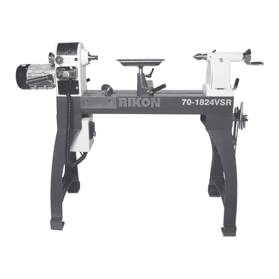
70-1824VSR
70-1824VSR2
18" x 24" VSR Lathes
1.75HP, 115V and 2.5HP, 230V Models
Operator's Manual
Record the serial number and date of purchase in your manual for future reference.
The serial number can be found on the specification label on the rear of your machine.
Serial Number: _________________________
Date of purchase: _________________________
For technical support or parts questions, email techsupport@rikontools.com or call toll free at (877) 884-5167
www.rikontools.com
70-1824VSRM3
Advertisement
Table of Contents

Related Manuals for Rikon Power Tools 70-1824VSR


Summary of Contents for Rikon Power Tools 70-1824VSR
- Page 1 70-1824VSR 70-1824VSR2 18” x 24” VSR Lathes 1.75HP, 115V and 2.5HP, 230V Models Operator’s Manual Record the serial number and date of purchase in your manual for future reference. The serial number can be found on the specification label on the rear of your machine.
-
Page 2: Table Of Contents
NOTE: The specifications, photographs, drawings and information in this manual represent the current model when the manual was prepared. Changes and improvements may be made at any time, with no obligation on the part of RIKON Power Tools, Inc. to modify previously delivered units. -
Page 3: Safety Instructions
SAFETY INSTRUCTIONS IMPORTANT! Safety is the single most important consideration in the operation of this equipment. The following instructions must be followed at all times. Failure to follow all instructions listed below may result in electric shock, fire, and/or serious personal injury. There are certain applications for which this tool was designed. - Page 4 SAFETY INSTRUCTIONS 12. KEEP PROTECTIVE GUARDS IN PLACE AND IN 25. ALWAYS WEAR A DUST MASK TO PREVENT WORKING ORDER. INHALING DANGEROUS DUST OR AIRBORNE PARTICLES, including wood dust, crystalline silica dust 13. AVOID ACCIDENTAL STARTING. Make sure that and asbestos dust. Direct particles away from face and the power switch is in the “OFF”...
- Page 5 SAFETY INSTRUCTIONS - 70-1824VSR EXTENSION CORDS ELECTRICAL SAFETY THE USE OF AN EXTENSION CORD THIS 115V TOOL MUST BE GROUND- WITH THIS MACHINE IS NOT RECOMMENDED. For ED WHILE IN USE TO PROTECT THE OPERATOR FROM best power and safety, plug the machine directly into a ELECTRIC SHOCK.
- Page 6 SAFETY INSTRUCTIONS - 70-1824VSR2 ELECTRICAL SAFETY EXTENSION CORDS THIS TOOL REQUIRES THE USE OF USE OF AN EXTENSION CORD A 220V PLUG (NOT INCLUDED), AND MUST BE WITH THIS MACHINE IS NOT RECOMMENDED. FOR GROUNDED WHILE IN USE TO PROTECT THE BEST POWER AND SAFETY, PLUG THE MACHINE OPERATOR FROM ELECTRIC SHOCK.
- Page 7 SAFETY INSTRUCTIONS SPECIFIC SAFETY INSTRUCTIONS FOR WOOD LATHES This machine is intended for the shaping, smoothing and finishing of natural, solid woods. The permissible workpiece dimensions must be observed (see Technical Specification). Any other use not as specified, including modification of the machine or use of parts not tested and approved by the equipment manufacturer can cause unforeseen damage, and invalidate the warranty.
-
Page 8: Getting To Know Your Machine
Shown with faceplate. CONTENTS OF PACKAGE Model #70-1824VSR and 70-1824VSR2 Wood Lathes are shipped complete in one box. Unpacking and Clean-up 1. Carefully remove all contents from the shipping carton. Compare the contents with the list of contents to make sure that all of the items are accounted for, before discarding any packing material. -
Page 9: Installation
E. Tailstock Assembly F. Lathe Bed G. Electronic Controls H. Power Cord * 70-1824VSR Lathe shown. 70-1824VSR 115V includes the electrical plug. The 70-1824VSR2 230V does not include the plug. I. Bolts (6) & Washers (12) M. Wrenches (2) 8/10 &... -
Page 10: Assembly
29 & 36 (Sheet A part #4 is listed as #4A, etc.). INSTALL THE PADS OR FEET ONTO THE LEGS The 70-1824VSR Lathe has a floor-to-spindle height of approximately 43-5/16” (1100mm). If this working height is fine, then the lathe can be used as is. - Page 11 ASSEMBLY INSTALL THE LATHE BED ONTO THE LEGS 44” 1. Position the two Legs (O) approximately 44” (1118mm) apart measuring from the outside edges. Be sure that the shelf brackets on the legs are facing inward, towards each other. Figure 4. 2.
- Page 12 ASSEMBLY INSTALL THE TOOL REST Install the 12” long PRO Tool Rest (T) into the Tool Rest Base (also called a Banjo) (D). Secure the tool rest’s 1” diameter post in the base with the Adjustable Locking Handle (#2A). Figure 8, A. NOTE: The handle can be adjusted to any position for best opera- tion, loosening or tightening, or to set it at a spot that will not interfere with you while working.
-
Page 13: Operation
OPERATION HEADSTOCK CONTROLS THE MACHINE MUST NOT BE PLUGGED IN AND THE POWER SWITCH MUST BE IN THE A. SPINDLE LOCK BUTTON (FIG. 13, A) secures the OFF POSITION UNTIL ALL ADJUSTMENTS ARE COMPLETE. headstock spindle for the mounting or removal of face- plates or chucks. - Page 14 OPERATION HEADSTOCK SPUR CENTER The Spur Center (Q) is used for turning between centers. It fits into the spindle. Both spindle and the spur center have matching MT-2 tapers. The spur center can be removed from the spindle with the long Knockout Bar (K). Insert the knockout bar through the opposite, outboard left end of the spindle, and then hit the spur center’s back end to knock it out of the spindle.
- Page 15 MAIN ON/OFF SWITCH AC INVERTER CONTROL BOX The #70-1824VSR Lathe has a Main ON/OFF switch (Fig. 22, A) located on the inverter box which is under the head- stock end of the lathe bed. This switch MUST be oper- ated before and after the lathe is used. It allows electrical INVERTER access to the switch box for using the lathe.
- Page 16 PLUGGED IN AND THE POWER SWITCH MUST BE IN THE revolutions per minute (RPM). Spindle speeds are shown OFF POSITION UNTIL ALL ADJUSTMENTS ARE COMPLETE. 70-1824VSR + VSR2 Spindle Speed Label Diagram EFS 70x45.pdf 7/7/2022 9:36 on the LCD Display (E). See the Speed Chart below for the 3 speed range settings.
- Page 17 OPERATION LATHE BED EXTENSIONS - (OPTIONAL) The 70-1824VSR Lathe features a cast iron bed with three sides machined to add bed extensions which will expand the work capabilities for turning. NOTE: the only bed extension made to fit the specificatIons of the 70-1824VSR lathe is the #70-908.
-
Page 18: Adjustments
FIG. 31 motor. Figure 32. 6. Close the two front Belt Doors on the headstock to protect the belt, pulleys and internal working from dust. 70-1824VSR + VSR2 Spindle Speed Label Diagram EFS 70x45.pdf 7/7/2022 9:36:03 AM HANDLE PUSHED BACK IN LOCKED 7. - Page 19 ADJUSTMENTS SPINDLE INDEXING ADJUSTMENTS Conveniently located on the front of the headstock, the Index Pin Assembly (FIG. 34 & 35) is used to hold and position the spindle for making accurate, spaced pattern work on projects such as straight fluting, grooving, drilling, INDEXING detail carving, wood burning patterns and laying out designs POSITION...
- Page 20 ADJUSTMENTS ALIGNING SPINDLE CENTERS The alignment of the headstock spur center and the tail- stock live center are set at the factory, but this should be checked once the lathe is assembled and ready for use. 1. Slide the tailstock towards the headstock until the center point of the live center almost touches the headstock’s spur center.
- Page 21 ADJUSTMENTS CHANGING THE BELT Changing the belt requires that the headstock spindle be removed, or half removed, from the headstock casting. Then the new belt can be slipped over the spindle and down inside of the headstock to the motor pulley. 1.
- Page 22 OFF POSITION UNTIL ALL ADJUSTMENTS ARE COMPLETE. USING MAGNETIC BASE LIGHTS & ACCESSORIES The 70-1824VSR lathe is designed with flat headstock and tailstock metal surfaces for attaching magnetic based lights, storage bowls or other acces- sories. The headstock lid is fitted with a steel plate just for this purpose. The OPTIONAL cast iron tailstock’s top surface offers a generous 8-1/4”...
-
Page 23: Maintenance
A general cleaning should be done after every use to avoid future problems and ensure that the 7. When not in use, make sure that the #70-1824VSR’s machine is in ready condition for its next use. Main ON/OFF Switch that is located on the lathe’s inverter box is turned off. - Page 24 WIRING DIAGRAM...
- Page 25 WIRING DIAGRAM...
-
Page 26: Troubleshooting
TROUBLESHOOTING ELECTRONIC SPEED CONTROL ACTION CODES CODE CODE CONDITION SOLUTION Over current 1. Power off and wait 5 minutes before restarting 2. Check the load on the motor 3. Check if Index Pin or turnings are preventing spindle rotation 4. If you can not return to normal contact Customer Service Over voltage 1. - Page 27 TROUBLESHOOTING REMEDY PROBLEM PROBABLE CAUSE 1. Machine is not plugged in 1. Plug in machine Motor will not start 2. Main on/off switch is in ‘off’ position 2. Turn main on/off switch to ‘on’ 3. Low voltage or loose connection 3.
-
Page 28: Notes
TROUBLESHOOTING CONTINUED FROM PAGE 27 REMEDY PROBLEM PROBABLE CAUSE 1. Dust buildup on RPM reader 1. Blow off dust from RPM reader Digital readout does not work 2. Digital readout sensor out of position 2. Adjust the sensor with the RPM reader 3. -
Page 29: Parts Diagrams & Parts Lists
PARTS DIAGRAM & PARTS LIST TOOL REST BASE ASSEMBLY SHEET A KEY NO. DESCRIPTION PART NO. QUANTITY 12” Tool rest assembly 70-978, 70-970, 70-966 1 Each (see Page 37) Locking handle P70-1824VSR-2A Handle P70-1824VSR-3A Hex lock nut M12 P70-1824VSR-4A Washer 12 P70-1824VSR-5A Position plate P70-1824VSR-6A... - Page 30 PARTS DIAGRAM HEADSTOCK ASSEMBLY - SHEET B...
- Page 31 PARTS LIST HEADSTOCK ASSEMBLY - SHEET B...
- Page 32 PARTS DIAGRAM & PARTS LIST LATHE BED ASSEMBLY - SHEET C NOTE: Please reference the Manufacturer’s Part Number when calling for Replacement Parts. For Parts under Warranty, the Serial Number of your machine is required. KEY NO. DESCRIPTION PART NO. QTY.
- Page 33 PARTS DIAGRAM & PARTS LIST TAILSTOCK ASSEMBLY SHEET D 12 13 18 19 20 NOTE: Please reference the Manufacturer’s Part Number when calling for Replacement Parts. For Parts under Warranty, the Serial Number of your machine is required. DESCRIPTION PART NO. QTY.
- Page 34 PARTS DIAGRAM & PARTS LIST LATHE BASE ASSEMBLY SHEET E NOTE: Please reference the Manufacturer’s Part Number when calling for Replacement Parts. For Parts under Warranty, the Serial Number of your machine is required. KEY NO. DESCRIPTION PART NO. QTY. P70-1824VSR-1E Hex socket head cap screw M10x30 P70-1824VSR-2E...
- Page 35 PARTS DIAGRAM & PARTS LIST SWITCH BOX ASSEMBLY SHEET F NOTE: Please reference the Manufacturer’s Part Number when calling for Replacement Parts. For Parts under Warranty, the Serial Number of your machine is required. DESCRIPTION PART NO. QTY. DESCRIPTION PART NO. QTY.
- Page 36 PARTS DIAGRAM & PARTS LIST CONTROL BOX ASSEMBLY SHEET G DESCRIPTION PART NO. QTY. DESCRIPTION PART NO. QTY. P70-1824VSR-10-2G Crs recess pan hd screw M4x10 P70-1824VSR-1G 10.2G Plug cable 230V (VSR2) P70-1824VSR-11G Switch P70-1824VSR-2G Filter P70-1824VSR-12G Hex sokt rnd hd screw M6x10 P70-1824VSR-3G Controller box P70-1824VSR-13G...
-
Page 37: Accessories
70-908 16” BED EXTENSION This 16” long cast iron lathe bed extension installs on the 70-1824VSR lathe in 3 different locations! 1) Mounted on the end of the bed, it increases center- to-center length from 24” to 40”. 2) Mounted on the... - Page 38 SPINDLE WASHER with the supplied USB cord Rubber Multi-V drive belt and electrical outlet converter Install on 1-1/4” x 8TPI for the 70-1824VSR (not included). Includes a side lathe spindles for easier and 70-1824VSR2 clip with magnetic back for removal of faceplates and alternative mounting options lathes.
-
Page 39: Warranty
® 5-Year Limited Warranty RIKON Power Tools Inc. (“Seller”) warrants to only the original retail consumer/purchaser of our products that each product be free from defects in materials and workmanship for a period of five (5) years from the date the product was purchased at retail. This warranty may not be transferred. - Page 40 70-1824VSR 70-1824VSR2 For more information: 25 Commerce Way North Andover, MA 01845 877-884-5167 / 978-528-5380 techsupport@rikontools.com LINK TO RIKON WEBSITE www.rikontools.com 70-1824VSRM3...
Need help?
Do you have a question about the 70-1824VSR and is the answer not in the manual?
Questions and answers