Advertisement
Table of Contents
- 1 Table of Contents
- 2 Specifications
- 3 Safety Instructions
- 4 Electricals & Wiring Diagram
- 5 Contents of Package
- 6 Getting to Know Your Machine
- 7 Installation
- 8 Assembly
- 9 Operation
- 10 Adjustments
- 11 Maintenance
- 12 Troubleshooting
- 13 Parts Diagram & Parts List
- 14 Accessories
- 15 Notes
- 16 Warranty
- Download this manual
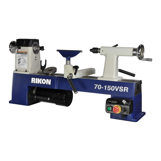
70-150VSR
12" x 16-1/2" Midi VSR Lathe
Operator's Manual
Record the serial number and date of purchase in your manual for future reference.
The serial number can be found on the specification label on the rear of your machine.
Serial Number: _________________________
Date of purchase: _________________________
For technical support or parts questions, email techsupport@rikontools.com or call toll free at (877) 884-5167
www.rikontools.com
70-150VSRM1
Advertisement
Table of Contents

Subscribe to Our Youtube Channel
Related Manuals for Rikon Power Tools 70-150VSR


Summary of Contents for Rikon Power Tools 70-150VSR
- Page 1 70-150VSR 12” x 16-1/2” Midi VSR Lathe Operator’s Manual Record the serial number and date of purchase in your manual for future reference. The serial number can be found on the specification label on the rear of your machine. Serial Number: _________________________ Date of purchase: _________________________ For technical support or parts questions, email techsupport@rikontools.com or call toll free at (877) 884-5167...
-
Page 2: Table Of Contents
Changes and improvements may be made at any time, with no obligation on the part of Rikon Power Tools, Inc. to modify previously delivered units. Reasonable care has been taken to ensure that the information in this manual is correct, to provide you with the guidelines for the proper safety,... -
Page 3: Safety Instructions
SAFETY INSTRUCTIONS IMPORTANT! Safety is the single most important consideration in the operation of this equipment. The following instructions must be followed at all times. Failure to follow all instructions listed below may result in electric shock, fire, and/or serious personal injury. There are certain applications for which this tool was designed. - Page 4 SAFETY INSTRUCTIONS 12. KEEP PROTECTIVE GUARDS IN PLACE AND IN 25. ALWAYS WEAR A DUST MASK TO PREVENT WORKING ORDER. INHALING DANGEROUS DUST OR AIRBORNE PARTICLES, including wood dust, crystalline silica dust 13. AVOID ACCIDENTAL STARTING. Make sure that and asbestos dust. Direct particles away from face and the power switch is in the “OFF”...
-
Page 5: Electricals & Wiring Diagram
SAFETY INSTRUCTIONS EXTENSION CORDS ELECTRICAL SAFETY THE USE OF AN EXTENSION CORD THIS TOOL MUST BE GROUNDED WITH THIS MACHINE IS NOT RECOMMENDED. For WHILE IN USE TO PROTECT THE OPERATOR FROM best power and safety, plug the machine directly into a ELECTRIC SHOCK. - Page 6 SAFETY INSTRUCTIONS SPECIFIC SAFETY INSTRUCTIONS FOR WOOD LATHES This machine is intended for the shaping, smoothing and finishing of natural, solid woods. The permissible workpiece dimensions must be observed (see Technical Specification). Any other use not as specified, including modification of the machine or use of parts not tested and approved by the equipment manufacturer can cause unforeseen damage, and invalidate the warranty.
-
Page 7: Contents Of Package
ADDITIONAL TOOLS REQUIRED FOR ASSEMBLY & ADJUSTMENTS #2 Phillips Screwdriver Adjustable Wrench Model 70-150VSR Wood Lathe is shipped complete in one box. Unpacking and Clean-up 1. Carefully remove all contents from the shipping carton. Compare the contents with the list of contents to make sure that all of the items are accounted for, before discarding any packing material. -
Page 8: Getting To Know Your Machine
ASSEMBLY The 70-150VSR Lathe requires only minor assembly to 5. The Faceplate (M) may be shipped pre-installed on the become operational. See the photos above for reference. -
Page 9: Operation
OPERATION HEADSTOCK CONTROLS 1. HEADSTOCK SPINDLE LOCK: The spring loaded Index Pin Assembly (#29B, FIG. 1, A) is used to position the spindle for making accurate, spaced pattern work on projects such as straight fluting, grooving, drilling, detail carving, wood burning patterns and laying out designs. See page 14 for more information on indexing. - Page 10 OPERATION TOOL REST CONTROLS 1. TOOL REST BODY LOCK HANDLE: (FIG. 4, A) This cam action lever handle locks the tool rest base (B) down in position on the lathe bed. Unlock handle to position the tool rest in any location along the lathe bed. Tighten the handle when the tool rest is properly located for safe turning of the workpiece.
- Page 11 LATHE BED EXTENSIONS - (OPTIONAL) The 70-150VSR Lathe features a cast iron bed with both of its ends machined to add bed extensions which will expand the work capabilities for turning. Extensions easily bolt onto the lathe ends for solid support.
-
Page 12: Adjustments
ADJUSTMENTS THE MACHINE MUST NOT BE PLUGGED IN AND THE POWER SWITCH MUST BE IN THE OFF POSITION UNTIL ALL ADJUSTMENTS ARE COMPLETE. CHANGING BELT SPEEDS LOCKED 1. Unplug the lathe from the power source. HANDLE 2. Open the top Headstock Cover (#14B, FIG. 10, A) and the left side, Bed Cover Plate Door (#4A, B) to gain access to the belt and pulleys that are inside of the headstock. - Page 13 ADJUSTMENTS CHANGING THE BELT Changing the belt requires that the headstock spindle be removed, or half removed, from the headstock casting. Then the new belt can be slipped over the spindle and down inside of the headstock to the motor pulley. LOCKED HANDLE 1.
- Page 14 ADJUSTMENTS CHANGING THE BEARINGS THE MACHINE MUST NOT BE To change the bearings, the whole spindle shaft needs to PLUGGED IN AND THE POWER SWITCH MUST BE IN THE be shifted right, out of the headstock, towards the tailstock. OFF POSITION UNTIL ALL ADJUSTMENTS ARE COMPLETE. Then the bearings can be removed from the headstock casting.
-
Page 15: Maintenance
- Turn off the machine and re-start it once the digital display Spindle Direction Protection Mode - The spindle direction has been changed during operation. has cleared. See page 21 for the 70-150VSR Wiring Diagram, and page 5 for additional electrical information. NOTES... -
Page 16: Troubleshooting
TROUBLESHOOTING REMEDY PROBLEM PROBABLE CAUSE Motor will not start 1. Machine is not plugged in 1. Plug in machine 2. Low voltage 2. Check fuses 3. Loose connection 3. Check plug and all connections Motor fails to develop full power. 1. -
Page 17: Parts Diagram & Parts List
PARTS DIAGRAM & PARTS LIST 6B010000 床身组件 Sheet 70-150VSR BED ASSEMBLY SHEET A NOTE: Please reference the Part Number when calling for Replacement Parts. For Parts under Warranty, the Serial Number of your machine is required. PART DESCRIPTION Motor connecting plate... - Page 18 WL1216B020000 机头箱组件 Sheet PARTS LIST & PARTS LIST 70-150VSR HEADSTOCK ASSEMBLY - SHEET B 15 16 17 18 NOTE: Please reference 25 26 27 the Part Number when calling for Replacement Parts. For Parts under Warranty, the Serial Number of your machine is required.
- Page 19 PARTS DIAGRAM & PARTS LIST 组件 Sheet 70-150VSR TAILSTOCK ASSEMBLY SHEET C See pages 10 and 12 for information on operating and adjusting the tailstock. PART DESCRIPTION Thread cap 70-150VSR-1C Handle sleeve 70-150VSR-2C Tailstock locking lever 70-150VSR-3C Locking handle 70-150VSR-4C...
- Page 20 刀架组件 Sheet PARTS DIAGRAMS & PARTS LISTS 70-150VSR TOOL REST ASSEMBLY SHEET D WL1216B093000 控制器组件 Sheet 70-150VSR CONTROLLER ASSEMBLY PART DESCRIPTION SHEET E Threaded cap end 70-150VSR-1D Handle sleeve 70-150VSR-2D Eccentric handle 70-150VSR-3D Circlip 70-150VSR-4D Tool rest (parts listed below) 6”...
-
Page 21: Accessories
Universal, all-steel Stand This short, cast iron extension bolts to the left, head- Extension bolts onto the stock end of the 70-150VSR Lathe for outboard 70-910 and 70-920 stands turning. It extends the lathe’s swing diameter capacity to support lathes with Bed from 12”... -
Page 22: Notes
ACCESSORIES 70-942 60° LIVE CENTER RIKON PRO TOOL RESTS Great for centering stock with 1/8” to 1-3/8” pre-drilled end holes for turning. Features sealed double ball Interchangeable bearings for smooth turning Tool Rest operation, Tops and Posts let #2 Morse you mix and match Taper and parts to meet the tool... -
Page 23: Warranty
® 5-Year Limited Warranty RIKON Power Tools Inc. (“Seller”) warrants to only the original retail consumer/purchaser of our products that each product be free from defects in materials and workmanship for a period of five (5) years from the date the product was purchased at retail. This warranty may not be transferred. - Page 24 70-150VSR For more information: 16 Progress Road Billerica, MA 01821 877-884-5167 / 978-528-5380 techsupport@rikontools.com LINK TO RIKON WEBSITE www.rikontools.com 70-150VSRM1...
Need help?
Do you have a question about the 70-150VSR and is the answer not in the manual?
Questions and answers