Table of Contents
Advertisement
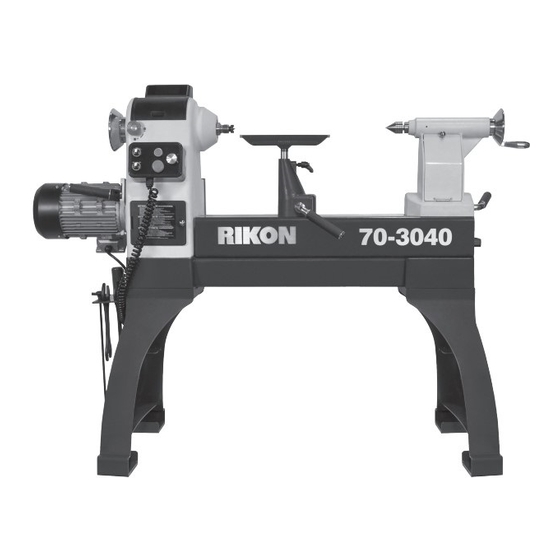
70-3040
30"x40" Heavy Duty 3HP VSR Lathe
with Sliding Bed
Operator's Manual
Record the serial number and date of purchase in your manual for future reference.
The serial number can be found on the specification label on the rear of your machine.
Serial Number: _________________________
Date of purchase: _________________________
For technical support or parts questions, email techsupport@rikontools.com or call toll free at (877) 884-5167
www.rikontools.com
70-3040M1
Advertisement
Table of Contents

Related Manuals for Rikon Power Tools 70-3040


Summary of Contents for Rikon Power Tools 70-3040
- Page 1 70-3040 30”x40” Heavy Duty 3HP VSR Lathe with Sliding Bed Operator’s Manual Record the serial number and date of purchase in your manual for future reference. The serial number can be found on the specification label on the rear of your machine.
-
Page 2: Table Of Contents
Changes and improvements may be made at any time, with no obligation on the part of Rikon Power Tools, Inc. to modify previously delivered units. Reasonable care has been taken to ensure that the information in this manual is correct, to provide you with the guidelines for the proper safety,... -
Page 3: Safety Instructions
SAFETY INSTRUCTIONS IMPORTANT! Safety is the single most important consideration in the operation of this equipment. The following instructions must be followed at all times. Failure to follow all instructions listed below may result in electric shock, fire, and/or serious personal injury. There are certain applications for which this tool was designed. - Page 4 SAFETY INSTRUCTIONS 12. KEEP PROTECTIVE GUARDS IN PLACE AND IN 25. ALWAYS WEAR A DUST MASK TO PREVENT WORKING ORDER. INHALING DANGEROUS DUST OR AIRBORNE PARTICLES, including wood dust, crystalline silica dust 13. AVOID ACCIDENTAL STARTING. Make sure that and asbestos dust. Direct particles away from face and the power switch is in the “OFF”...
-
Page 5: Electricals & Wiring Diagram
* Canadian electrical codes require extension cords to NOTE: The WIRING DIAGRAM for the #70-3040 Lathe be certified SJT type or better. is listed on Page 20. - Page 6 SAFETY INSTRUCTIONS SPECIFIC SAFETY INSTRUCTIONS FOR WOOD LATHES This machine is intended for the shaping, smoothing and finishing of natural, solid woods. The permissible workpiece dimensions must be observed (see Technical Specification). Any other use not as specified, including modification of the machine or use of parts not tested and approved by the equipment manufacturer can cause unforeseen damage, and invalidate the warranty.
-
Page 7: Getting To Know Your Machine
Extension CONTENTS OF PACKAGE Model #70-3040 Heavy Duty VSR Wood Lathe is shipped complete in one box. Unpacking and Clean-up 1. Carefully remove all contents from the shipping carton. Compare the contents with the list of contents to make sure that all of the items are accounted for, before discarding any packing material. -
Page 8: Installation
CONTENTS OF PACKAGE CONTENTS OF PACKAGE Lathe Bed Assembly A. Motor Assembly B. Electronic Controls C. Headstock Assembly D. Tool Rest Base Assembly E. Tailstock Assembly F. Lathe’s Upper Sliding Bed G. Lathe Bed U. Wrenches (2) 13/16 & H. Legs (2) M. -
Page 9: Assembly
23 & 29 (Sheet A part #4 is listed as #A4, etc.). INSTALL THE PADS OR FEET ONTO THE LEGS The 70-3040 Lathe has a floor-to-spindle height of 44”. If this working height is fine, then the lathe can be used as is. - Page 10 ASSEMBLY INSTALL THE LATHE BED ONTO THE LEGS THE MACHINE MUST NOT BE 1. Position the two Legs (H, #F1) approximately 45-1/4” PLUGGED IN AND THE POWER SWITCH MUST BE IN THE apart measuring from the outside edges. Be sure that the OFF POSITION UNTIL ASSEMBLY IS COMPLETE.
-
Page 11: Operation
ASSEMBLY INSTALL THE TOOL HOLDER Install the Tool Holder (P, #F5) onto the outside surface of either the left or right Leg (H, #F1) with the two Washers and hex head mounting Screws (P,#F6,7) provided. This holder includes multiple holes for convenient stor- age of wrenches, centers, tool rests and other lathe accessories. - Page 12 OPERATION TAILSTOCK CONTROLS - Figure 12 C. TAILSTOCK LOCK HANDLE: Locks the tailstock in position along the length of the lathe bed. Unlock handle to position the tool rest to move the tailstock. Tighten handle when properly positioned. See page 17 for instructions on how to adjust the locking tension.
- Page 13 OPERATION MAIN ON / OFF SWITCH The #70-3040 Lathe has a main on/off switch located behind the headstock on the side of the metal Inverter Box. FIG. 16. This switch MUST be operated before and after the lathe is used. It allows electrical access to the control box for using the lathe.
- Page 14 See page 13 & 14 for instructions on operating the elec- tronic controls for moving the upper motorized sliding bed. The unique Sliding Bed feature of RIKON’s #70-3040 lathe expands the working capacities of the lathe with a twist of a dial.
-
Page 15: Adjustments
OPERATION Option 2: The ‘Gap’ on the lathe bed (FIG. 22) can be filled with RIKON’s Gap Bed Insert accessory (FIG. 24). This GAP BED short, duplication of the lathe’s upper lathe bed installs over INSERT the exposed lower bed and continues the upper bed track at the same height as the sliding bed. - Page 16 6. Close the two front Belt Doors on the headstock to HANDLE PUSHED BACK protect the belt, pulleys and internal working from dust. IN LOCKED POSITION 70-3040 Spindle Speed Label Diagram EFS.pdf 1 7/2/2019 11:51:44 AM 7. Plug the lathe back into the power source. Label 70mm x 115mm Black...
- Page 17 ADJUSTMENTS SPINDLE INDEXING ADJUSTMENTS NEVER START THE LATHE WITH THE INDEX PIN ENGAGED IN THE SPINDLE, OR The Headstock Spindle has 36 indexing holes, each 10° DAMAGE TO THE MACHINE WILL RESULT. apart, which allows accurate pattern work on projects such as straight fluting, grooving, drilling, detail carving, wood burning patterns, laying out designs and more.
- Page 18 ADJUSTMENTS CHANGING THE BELT HANDLE PULLED FORWARD Changing the belt requires that the headstock spindle be AND DOWN TO LOOSEN removed, or half removed, from the headstock casting. BELT TENSION Then the new belt can be slipped over the spindle and down inside of the headstock to the motor pulley.
-
Page 19: Maintenance
8. When not in use, make sure that the #70-3040’s Main 3. Keep the lathe beds free of resin and rust. Clean them ON/OFF Switch that is located on the lathe’s inverter box regularly with a non-flammable solvent, then coat with a is turned off. - Page 20 WIRING DIAGRAM...
-
Page 21: Troubleshooting
TROUBLESHOOTING REMEDY PROBLEM PROBABLE CAUSE 1. Machine is not plugged in 1. Plug in machine Motor will not start 2. Main on/off switch is in ‘off’ position 2. Turn main on/off switch to ‘on’ 3. Low voltage or loose connection 3. -
Page 22: Notes
TROUBLESHOOTING CONTINUED FROM PAGE 21 REMEDY PROBLEM PROBABLE CAUSE 1. Blow off dust from RPM reader 1. Dust buildup on RPM reader Digital readout does not work 2. Digital readout sensor out of position 2. Adjust the sensor with the RPM reader 3. -
Page 23: Parts Diagrams & Parts Lists
PARTS DIAGRAM & PARTS LIST TOOL REST BASE ASSEMBLY SHEET A KEY NO. DESCRIPTION PART NO. QUANTITY 12” Tool rest assembly 70-978, 70-970, 70-966 (see Page 30) Locking handle P70-3040-2A Handle P70-3040-3A Sleeve P70-3040-4A End cap P70-3040-5A Hexagon lock nut M12 P70-3040-6A Washer P70-3040-7A... - Page 24 PARTS DIAGRAM...
- Page 25 PARTS LIST HEADSTOCK ASSEMBLY - SHEET B...
- Page 26 PARTS DIAGRAM & PARTS LIST...
- Page 27 尾座组件 Sheet PARTS DIAGRAM & PARTS LIST TAILSTOCK ASSEMBLY SHEET D NOTE: Please reference the Manufacturer’s Part Number when calling for Replacement Parts. 20 19 For Parts under Warranty, the Serial Number of your machine is required. 13 12 DESCRIPTION PART NO.
- Page 28 0300 下床身组件 Sheet PARTS DIAGRAM & PARTS LIST LATHE BED ASSEMBLY SHEET E NOTE: Please reference the Manufacturer’s Part Number when calling for Replacement Parts. For Parts under Warranty, the Serial Number of your machine is required. DESCRIPTION PART NO. QTY.
- Page 29 A100000 支腿组件 Sheet PARTS DIAGRAM & PARTS LIST LATHE BASE ASSEMBLY SHEET F NOTE: Please reference the Manufacturer’s Part Number when calling for Replacement Parts. For Parts under Warranty, the Serial Number of your machine is required. KEY NO. DESCRIPTION PART NO.
-
Page 30: Accessories
70-937 6” Diameter 70-907 GAP BED INSERT This short, duplication of the 70-3040 lathe’s upper lathe bed installs over the exposed lower bed and continues the upper bed track at the same height as the sliding bed. This means that your tool rest base can be now positioned anywhere on the lathe for turn- ing, sliding from end-to-end, between center-to-center. -
Page 31: Warranty
® RIKON Power Tools Inc. (“Seller”) warrants to only the original retail consumer/purchaser of our products that each product be free from defects in materials and workmanship for a period of five (5) years from the date the product was purchased at retail. - Page 32 70-3040 For more information: 16 Progress Road Billerica, MA 01821 877-884-5167 / 978-528-5380 techsupport@rikontools.com LINK TO RIKON WEBSITE www.rikontools.com 70-3040M1...
Need help?
Do you have a question about the 70-3040 and is the answer not in the manual?
Questions and answers