Table of Contents
Advertisement
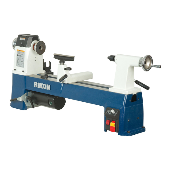
70-220VSR
12-1/2" x 20" MIDI VSR Lathe
4001824
Operator's Manual
Record the serial number and date of purchase in your manual for future reference.
Serial Number: _________________________
Date of purchase: _________________________
For technical support or parts questions, email techsupport@rikontools.com or call toll free at (877)884-5167
www.rikontools.com
70-220VSRM6
Advertisement
Table of Contents

Subscribe to Our Youtube Channel
Related Manuals for Rikon Power Tools 70-220VSR


Summary of Contents for Rikon Power Tools 70-220VSR
- Page 1 70-220VSR 12-1/2” x 20” MIDI VSR Lathe 4001824 Operator’s Manual Record the serial number and date of purchase in your manual for future reference. Serial Number: _________________________ Date of purchase: _________________________ For technical support or parts questions, email techsupport@rikontools.com or call toll free at (877)884-5167 www.rikontools.com...
-
Page 2: Table Of Contents
Changes and improvements may be made at any time, with no obligation on the part of Rikon Power Tools, Inc. to modify previously delivered units. Reasonable care has been taken to ensure that the information in this manual is correct, to provide you with the guidelines for the proper safety,... -
Page 3: Safety Instructions
SAFETY INSTRUCTIONS IMPORTANT! Safety is the single most important consideration in the operation of this equipment. The following instructions must be followed at all times. Failure to follow all instructions listed below may result in electric shock, fire, and/or serious personal injury. There are certain applications for which this tool was designed. - Page 4 SAFETY INSTRUCTIONS 12. KEEP PROTECTIVE GUARDS IN PLACE AND IN 25. ALWAYS WEAR A DUST MASK TO PREVENT WORKING ORDER. INHALING DANGEROUS DUST OR AIRBORNE PARTICLES, including wood dust, crystalline silica dust 13. AVOID ACCIDENTAL STARTING. Make sure that and asbestos dust. Direct particles away from face and the power switch is in the “OFF”...
-
Page 5: Electricals & Wiring Diagram
SAFETY INSTRUCTIONS EXTENSION CORDS ELECTRICAL SAFETY THE USE OF AN EXTENSION CORD THIS TOOL MUST BE GROUNDED WITH THIS MACHINE IS NOT RECOMMENDED. For WHILE IN USE TO PROTECT THE OPERATOR FROM best power and safety, plug the machine directly into a ELECTRIC SHOCK. - Page 6 SAFETY INSTRUCTIONS SPECIFIC SAFETY INSTRUCTIONS FOR WOOD LATHES This machine is intended for the shaping, smoothing and finishing of natural, solid woods. The permissible workpiece dimensions must be observed (see Technical Specification). Any other use not as specified, including modification of the machine or use of parts not tested and approved by the equipment manufacturer can cause unforeseen damage.
-
Page 7: Contents Of Package
ADDITIONAL TOOLS REQUIRED FOR ASSEMBLY & ADJUSTMENTS #2 Phillips Screwdriver Adjustable Wrench Model 70-220VSR Wood Lathe is shipped complete in one box. Unpacking and Clean-up 1. Carefully remove all contents from the shipping carton. Compare the contents with the list of contents to make sure that all of the items are accounted for, before discarding any packing material. -
Page 8: Getting To Know Your Machine
ASSEMBLY 5. Install the 8” Tool Rest into the Tool Rest Base. The 70-220VSR Lathe requires only minor assembly to become operational. See the photos above for reference. 6. The Faceplate is shipped pre-installed on the headstock spindle. -
Page 9: Operation
OPERATION HEADSTOCK CONTROLS 1. HEADSTOCK SPINDLE LOCK: The spring loaded Index Pin Assembly (#44, FIG. 1, A) is primarily used to po- sition the spindle for making accurate, spaced pattern work on projects such as straight fluting, grooving, drilling, detail carving, wood burning patterns and laying out designs. -
Page 10: Tailstock Controls
OPERATION TOOL REST CONTROLS 1. TOOL REST BODY LOCK HANDLE: (FIG. 4, A) This cam action lever handle locks the tool rest base (B) down in position on the lathe bed. Unlock handle to position the tool rest in any location along the lathe bed. Tighten the handle when the tool rest is properly located for safe turning of the workpiece. -
Page 11: Adjustments
ADJUSTMENTS THE MACHINE MUST NOT BE PLUGGED IN AND THE POWER SWITCH MUST BE IN THE OFF POSITION UNTIL ALL ADJUSTMENTS ARE COMPLETE. CHANGING BELT SPEEDS 1. Unplug the lathe from the power source. 2. Open the top Headstock Cover (#35, FIG. 7, A) and the left side, Bed Cover Plate Door (#8, B) to gain access to the belt and pulleys that are inside of the headstock. - Page 12 ADJUSTMENTS CHANGING THE BELT To change the belt, the whole spindle shaft needs to be shifted right, out of the headstock, towards the tailstock. This will allow the new belt to be slipped over the spindle and onto the spindle pulley. Then the whole spindle shaft assembly can be re-installed so turning can be resumed.
- Page 13 ADJUSTMENTS CHANGING THE BEARINGS THE MACHINE MUST NOT BE To change the b earings, the whole spindle shaft needs to PLUGGED IN AND THE POWER SWITCH MUST BE IN THE be shifted right, out of the headstock, towards the tailstock. OFF POSITION UNTIL ALL ADJUSTMENTS ARE COMPLETE.
-
Page 14: Maintenance
MAINTENANCE Turn the power switch “OFF” and disconnect the plug from the outlet prior to adjusting or maintaining the machine. DO NOT attempt to repair or maintain the electrical components of the motor. Contact a qualified service technician for this type of maintenance. 3. - Page 15 TROUBLESHOOTING REMEDY PROBLEM PROBABLE CAUSE Motor will not start 1. Machine is not plugged in 1. Plug in machine 2. Low voltage 2. Check fuses 3. Loose connection 3. Check plug and all connections Motor fails to develop full power. 1.
- Page 16 PARTS DIAGRAM...
- Page 17 PARTS LIST DESCRIPTION MFG. PART NO. KEY NO. 1-JMWL1203010002-076L Hexagon socket cap screw 1-M6X30GB70B Flat washer 1-WSH6GB97D1B Lock washer 1-WSH6GB93B Tool holder 1-JL93010017-001S Cross pan head screw 1-M6X12GB818B Countersunk head screw 1-M4X10GB819B Bed cover plate door 1-JMWL1203011000-076U Countersunk head screw 1-M4X12GB819Z Magnet 1-JMWL1203010006...
- Page 18 PARTS DIAGRAM...
- Page 19 PARTS LIST...
-
Page 20: Parts Diagram & Parts List
PARTS DIAGRAM & PARTS LIST 70-220VSR CONTROL BOX ASSEMBLY 61 63D KEY NO. DESCRIPTION MFG. PART NO. Tapping screw 1-ST4D2X13GB845B Plastic electric box cover 1-JMWL1203090003-001S M20 Pull off 1-DJJH7120 M16 Pull off 1-JL91046300 Plastic electric box 1-JMWL1203090002-001S Control box assembly... -
Page 21: Accessories
70-901 24” LATHE BED EXTENSION 70-920 LATHE STAND Made of heavy cast iron, it bolts to the right end of the Universal, all-steel 70-220VSR Midi Lathe to extend the lathe’s working Stand adjusts from spindle length capacity to 44”. 23-1/4” to 37-1/4” long, and 24-1/2”... -
Page 22: Notes
NOTES Use this section to record Maintenance, Service and any calls to Technical Support:... -
Page 23: Warranty
WARRANTY 5-Year Limited Warranty RIKON Power Tools Inc. (“Seller”) warrants to only the original retail consumer/purchaser of our products that each product be free from defects in materials and workmanship for a period of five (5) years from the date the product was purchased at retail. This warranty may not be transferred. - Page 24 70-220VSR For more information: 16 Progress Road Billerica, MA 01821 877-884-5167 / 978-528-5380 techsupport@rikontools.com www.rikontools.com 70-220VSRM6...
Need help?
Do you have a question about the 70-220VSR and is the answer not in the manual?
Questions and answers