Table of Contents
Troubleshooting

Related Manuals for Metcal RSS-1000-CVSI-NC


Summary of Contents for Metcal RSS-1000-CVSI-NC
- Page 1 USER MANUAL, RSS-1000-CVSI 7000-5970 Rev. page Robotic Soldering System RSS-1000-CVSI User Manual 99 Washington Street Melrose, MA 02176 Phone 781-665-1400 Toll Free 1-800-517-8431 Visit us at www.TestEquipmentDepot.com...
- Page 2 USER MANUAL, RSS-1000-CVSI 7000-5970 Rev. page Copyright © 2018 OK International, Inc. PROPRIETARY NOTICE: This document contains proprietary data of OK International, Inc. The receipt or possession of this document does not convey any rights to reproduce it, disclose its contents, or to manufacture the concepts and details disclosed by this document.
-
Page 3: Table Of Contents
USER MANUAL, RSS-1000-CVSI 7000-5970 Rev. page Table of Contents SAFETY AND REGULATORY INFORMATION..................... 7 WARNING ................................. 7 OTHER SAFETY TIPS ............................ 8 SPECIFICATIONS ............................... 9 INTRODUCTION AND GENERAL OVERVIEW ................... 12 SYSTEM ARCHITECTURE ..........................13 ... - Page 4 USER MANUAL, RSS-1000-CVSI 7000-5970 Rev. page SAFETY FEATURES ............................ 69 Z-LIMIT SAFETY ............................69 CLEARANCE HEIGHT SAFETY....................... 78 CONNECTION VALIDATION (CV) SAFETY FEATURES ..............82 CLEAR INDICATORS RADIO FREQUENCY IS ACTIVE ..............82 AUTOMATIC RF ACTIVATION/DEACTIVATION ................82 ...
- Page 5 USER MANUAL, RSS-1000-CVSI 7000-5970 Rev. page WAY POINTS ............................165 SOLDER WIRE FEEDER ADJUSTMENT ....................166 ADVANCED PROFILE FUNCTIONS ......................168 EDIT PROFILE ............................168 EDIT PROFILE OVERVIEW ........................ 168 SOLDER PARAMETER EDIT ......................170 ...
- Page 6 USER MANUAL, RSS-1000-CVSI 7000-5970 Rev. page IMAGE ZOOM ............................278 ESTABLISHING FIDUCIAL POINTS (Future Feature, Not Present in this Release) ......282 PATTERN RECOGNITION ........................286 Template Creation ........................... 287 Pattern Recognition Using Template ...................... 289 ...
-
Page 7: Safety And Regulatory Information
USER MANUAL, RSS-1000-CVSI 7000-5970 Rev. page SAFETY AND REGULATORY INFORMATION WARNING IN ORDER TO BE IN COMPLIANCE WITH REQUIREMENTS OF CE DIRECTIVES, THE ROBOTIC SOLDERING SYSTEM MUST BE EQUIPPED WITH THE AC-RSS-1KSC SAFETY COVER ACCESSORY. THE SAFETY INTERLOCK OF THE ENCLOSURE WILL AUTOMATICALLY CEASE ALL MOVEMENT AND HOME THE SYSTEM ONCE AN OPERATOR COMES IN CLOSE PROXIMITY OF THE WORKING ENVELOPE. -
Page 8: Other Safety Tips
USER MANUAL, RSS-1000-CVSI 7000-5970 Rev. page This HEAVY LIFTING symbol on the packaging warns the user to team lift the Robotic Soldering System during removal from packaging and installation on the workbench. This symbol appears next to the relevant information in the manual. ... -
Page 9: Specifications
USER MANUAL, RSS-1000-CVSI 7000-5970 Rev. page SPECIFICATIONS Microprocessor 64-bit Intel ® Atom™ E3826 Series SoC Core Logic Integrated Intel HD Graphics with Open Source Hardware- Accelerated Drivers for Linux OS 2GB DDR3L RAM - System Memory Memory 8 MB SPI Flash - System Firmware Memory Intel HD Graphics (1920x1080 max resolution) Video HDMI 1.4a (micro HDMI connector) - Page 10 USER MANUAL, RSS-1000-CVSI 7000-5970 Rev. page Power Supply & Soldering Iron Metcal CV-PS5200-R with Communications Port Application Dependent CV Cartridges Ambient Operating Temp. 10 to 40 °C Max. Enclosure Temp. 55 °C Input Line Voltage 100 – 240 VAC, Grounded Circuit...
- Page 11 USER MANUAL, RSS-1000-CVSI 7000-5970 Rev. page Solder Wire Feeder Solder Feeder Required Solder Feeder Speed 1.0mm/sec – 50mm/sec Solder Diameter 0.8mm Solder Feeder Resolution ± 1.5mm or ± 5% of value (whichever is greater) Options Nitrogen Optional, Plumbed Fume Extraction Optional, Plumbed Safety Curtain Optional...
-
Page 12: Introduction And General Overview
This systemic and objective approach provides repeatability and a measurable standard to the soldering process. For this reason, Metcal has raised the bar yet again by incorporating their revolutionary technology into a robotic platform to provide an automated solution with intelligence. -
Page 13: System Architecture
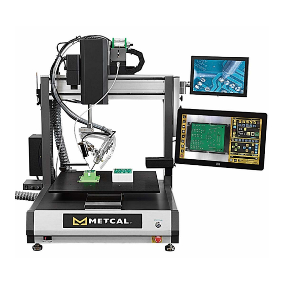
USER MANUAL, RSS-1000-CVSI 7000-5970 Rev. page SYSTEM ARCHITECTURE Computer Vision Camera Emergency Stop Button Tip Alignment Fixture Pause Button (N/A) CCD Witness Camera Solder Tip Cleaner Solder Wire Feeder Tube Adjustment Assembly Smart Interface Display Power “On” LED Fume Extraction Tube CCD Camera Power Switch &... - Page 14 USER MANUAL, RSS-1000-CVSI 7000-5970 Rev. page CV Power Supply Power Switch Nitrogen Inlet Monitor Adjustment Thumb Screws CCD Witness Camera 12V Power Connection Controller Box Power Connection Micro HDMI Connection Solder Wire Feeder Connection Ethernet Connection CCD Witness Camera Connection 6x USB Connections Inlet Power Connection Communications Cable...
-
Page 15: Tips Before Setting Up
USER MANUAL, RSS-1000-CVSI 7000-5970 Rev. page TIPS BEFORE SETTING UP The unit is very heavy! Please uncrate the unit with at least 2 people and using best lifting practices. DO NOT LIFT THE MAIN UNIT BY THE GANTRY OR TOP PLATE. LIFTING BY THE GANTRY OR TOP PLATE MAY DAMAGE THE ASSEMBLY! Before Setting Up Your Equipment... • Ensure your Robotic Soldering System has arrived complete • Provide a location that allows the user to operate this machine in a comfortable, well‐spaced environment Every Selective Soldering Robot has been factory assembled and calibrated. • Recalibration is not necessary after initial setup. • Verifying calibration and product functionality is strongly recommended prior to initial use. Power‐Up Sequence • Plug in all harnesses provided with unit. • Plug in all all power cords provided with unit. • Once all harnesses have been plugged in, you may power on unit. Be Mindful of Lighting! • Lighting can affect various camera functions within the software. ... -
Page 16: Unboxing Instructions
USER MANUAL, RSS-1000-CVSI 7000-5970 Rev. page UNBOXING INSTRUCTIONS 1. With proper Personal Protection Equipment (PPE), use an 8mm (5/16”) socket to remove all of the screws (16X) at the bottom of the crate. 2. With the assistance of a coworker or a mechanical lifting device, carefully lift lid of crate vertically and evenly using proper lifting techniques. - Page 17 USER MANUAL, RSS-1000-CVSI 7000-5970 Rev. page 4. Use a spanner wrench to remove the 4X 8mm hex nuts. 5. With the assistance of a coworker or a mechanical lifting device, carefully lift unit off pallet using proper lifting techniques. 5.1. Warning: Weight of unit is not evenly distributed. The back of the unit is heavier than the front.
- Page 18 USER MANUAL, RSS-1000-CVSI 7000-5970 Rev. page 7.2. Calibration Slider Block Assembly 7.3. End Effector 7.4. Head/Gantry...
- Page 19 USER MANUAL, RSS-1000-CVSI 7000-5970 Rev. page 7.5. Connection Validation Housing 7.5.1. Warning: Failure to remove foam from Connection Validation Housing may result in the overheating of the Connection Validation Power Supply 8. Replace Connection Validation Housing Cover once foam is removed Unboxing Complete!
-
Page 20: Controller Box Connections
USER MANUAL, RSS-1000-CVSI 7000-5970 Rev. page CONTROLLER BOX CONNECTIONS (Optional) (Optional) (Optional) OPEN... -
Page 21: Robot Base Connections
USER MANUAL, RSS-1000-CVSI 7000-5970 Rev. page ROBOT BASE CONNECTIONS N₂... -
Page 22: Robot Gantry Connections
USER MANUAL, RSS-1000-CVSI 7000-5970 Rev. page ROBOT GANTRY CONNECTIONS * ROBOT HEAD CONNECTION *Plug into an external outlet, see next page for instructions... -
Page 23: Cv Power Cable Connection Instructions
USER MANUAL, RSS-1000-CVSI 7000-5970 Rev. page CV POWER CABLE CONNECTION INSTRUCTIONS For units all units ordered, regardless of the configuration, please use an external outlet for powering the CV Power Supply at the rear of the unit. Outlet of which the CV Power Supply is to be plugged in to will vary depending on region. -
Page 24: Software Navigation
USER MANUAL, RSS-1000-CVSI 7000-5970 Rev. page SOFTWARE NAVIGATION LOGIN SCREEN Firmware Version Software Version Power Off Restart Cancel Controller Controller Admin Engineer Operator Login Login Login Main Login/Enter Power Button... -
Page 25: Main Screen Overview
USER MANUAL, RSS-1000-CVSI 7000-5970 Rev. page MAIN SCREEN OVERVIEW Header Solder Feeder Advance Options Profile Options Camera Tools Profile Options Connection Validation Display Main Toolbar Menu Bar Motion Controls Global Coordinate Display Status... -
Page 26: Main Menu Bar
USER MANUAL, RSS-1000-CVSI 7000-5970 Rev. page MAIN MENU BAR Main Menu Bar Create New Edit Profile Open Profile Save Profile Profile Pause Profile (Available only Run Profile Stop Profile Global Settings after run profile is activated.) Eject USB Emergency Stop... - Page 27 USER MANUAL, RSS-1000-CVSI 7000-5970 Rev. page Description of Functions Function Permissions Description The Create New Profile function allows the user to create a brand-new profile. Once this function is activated, the workspace will be cleared of any unsaved work. The Edit Profile function allows the operator to modify any existing profile or the current profile that is being created.
-
Page 28: Header Bar
USER MANUAL, RSS-1000-CVSI 7000-5970 Rev. page HEADER BAR Header Name of Profile CV Cartridge of Active in Workspace Profile Profile names and/or status of the profile will be displayed on the left of the header bar. CV cartridge name and/or status of the cartridge with respect to the profile will be displayed on the right of the header bar. - Page 29 USER MANUAL, RSS-1000-CVSI 7000-5970 Rev. page Profile Status Indicators Profile Display – New Profile Creation Appears when the Create New Profile function is utilized. Appears after any points are programmed into a profile. Upon completion of a run of the profile (live or dry run,) the robot will remain in the X, Y, and Θ coordinates of the last programmed point but shall move to the upper limit of the Z-Axis.
- Page 30 USER MANUAL, RSS-1000-CVSI 7000-5970 Rev. page CV Cartridge Status Indicators RF must be cycled On/Off once in order to activate this feature. Cycling the RF On/Off initializes the connection between the CV Power Supply and the robot after a complete power cycle of the unit. The default state upon bootup or when the new profile button has been tapped.
-
Page 31: Profile Options
USER MANUAL, RSS-1000-CVSI 7000-5970 Rev. page PROFILE OPTIONS Profile Options Solder Point Merge Profile Waypoint (Toggled under Waypoint) Solder Line Space Move Interpolation (Toggled under (Toggled under Move Waypoint) Interpolation) Undo Waypoint/ Redo Waypoint/ Record Point Pattern/ Line Pattern/ Line... - Page 32 USER MANUAL, RSS-1000-CVSI 7000-5970 Rev. page Description of Functions Function Permissions Description Merge profile allows users to insert previously programmed profiles into a new profile in locations defined by the user. Waypoints are user defined locations that can be programmed before or after a solder joint.
-
Page 33: Advance Profile Options
USER MANUAL, RSS-1000-CVSI 7000-5970 Rev. page ADVANCE PROFILE OPTIONS Advance Profile Options Set Go-To Generate Array Location... - Page 34 USER MANUAL, RSS-1000-CVSI 7000-5970 Rev. page Description of Functions Function Permissions Description Go-To Location allows users to record any position (X, Y, Z, & Θ) within the working envelope as a location for the robot to go to after each profile is complete. Every subsequent profile will start from this location as well.
-
Page 35: Solder Feeder Options
USER MANUAL, RSS-1000-CVSI 7000-5970 Rev. page SOLDER FEEDER OPTIONS Solder Feeder Options Pulse Solder Pulse Solder Feeder Test Solder Feed Feeder Forward Backward Solder Feeder Dry Run Toggled Dry Run Toggled Settings... - Page 36 USER MANUAL, RSS-1000-CVSI 7000-5970 Rev. page Description of Functions Function Permissions Description Pulses solder forward for the duration of the button press. Pulses solder backward for the duration of the button press. The Test Solder Feed button will feed the amount of solder at the speed that is set in the solder feeder parameters menu.
-
Page 37: Camera Tools
USER MANUAL, RSS-1000-CVSI 7000-5970 Rev. page CAMERA TOOLS Camera Tools Enable/Disable Take Screenshot Camera Open Image/ Pattern DXF/ Gerber Recognition... - Page 38 USER MANUAL, RSS-1000-CVSI 7000-5970 Rev. page Description of Functions Function Permissions Description Enables or Disables Camera. The teal icon signifies when the camera is in an enabled state, the grey icon signifies when the camera is in its disabled state. Upon shipment or during unboxing, the camera lens may lose focus.
-
Page 39: Connection Validation Display
USER MANUAL, RSS-1000-CVSI 7000-5970 Rev. page CONNECTION VALIDATION DISPLAY Connection Validation Display Tip Cartridge Installed on Robot Connection Validation Power Meter (Watts) Connection Active Temperature Validation Time-Out Display Counter Connection Connection Proper Grounding Validation Status Validation Time-Out Indicator Counter Toggle CV RF CV Graph CV Settings On/Off... - Page 40 USER MANUAL, RSS-1000-CVSI 7000-5970 Rev. page Description of Functions Function Permissions Description Connection Validation Settings include toggling between the temperature displayed in either degrees Celsius or degrees Fahrenheit and toggling the connection validation sound on/off. Connection Validation Graph button toggles between Net Power Meter (featured on previous page) and the Power Graph screen.
- Page 41 USER MANUAL, RSS-1000-CVSI 7000-5970 Rev. page Description of Functions Connection Validation Graph Number of Joints Current Temperature Soldered with Peak Power on Joint of Solder Tip Installed Cartridge Cartridge Serial Cartridge Production Number Lot Code Connection Validation Settings Celsius Toggled Fahrenheit Exit Toggled On...
- Page 42 USER MANUAL, RSS-1000-CVSI 7000-5970 Rev. page Description of Functions Function Permissions Description Displays the tip temperature in degrees Celsius. Displays the tip temperature in degrees Fahrenheit. Exits the screen Enables Connection Validation audio. Good joints are designated with a short beep while bad joints are designated with an extended chirping noise.
-
Page 43: Toolbar
USER MANUAL, RSS-1000-CVSI 7000-5970 Rev. page TOOLBAR Toolbar Motion Control (Fine & Coarse Absolute Position Home Speed Settings Adjustment Toggle) Tip Cleaning Offset Camera Zoom Nitrogen Parameters... - Page 44 USER MANUAL, RSS-1000-CVSI 7000-5970 Rev. page Description of Functions Function Permissions Description Motion control main menu is a directional pad for jogging and coarse adjustment. The button can be toggled for user defined fine adjustment. The icon will become gold when the menu is active, grey when another menu is active.
-
Page 45: Motion Control
USER MANUAL, RSS-1000-CVSI 7000-5970 Rev. page MOTION CONTROL Motion Controls Jog Top Plate Jog Head Left Jog Head Right Jog Top Plate Up Down Rotate Counter Jog End Effector Jog End Effector Rotate Clockwise Clockwise Θ Θ Θ Θ Quick-Snap: Quick-Snap: Quick-Snap: Quick-Snap:... - Page 46 USER MANUAL, RSS-1000-CVSI 7000-5970 Rev. page Description of Functions Function Permissions Description Jogs head left. This is a coarse adjustment and the distance travelled is dependent on the speed settings and how long of a button press occurs. Jogs head right. This is a coarse adjustment and the distance travelled is dependent on the speed settings and how long of a button press occurs.
- Page 47 USER MANUAL, RSS-1000-CVSI 7000-5970 Rev. page Description of Functions Function Permissions Description Θ Quick-Snap rotates end effector to the 0° position. 0° is defined as the position in which the end effector graduation marks are visible to the operator. This is an absolute command, or in other words, will automatically rotate to the 0°...
-
Page 48: Remaining Menus/ Buttons
USER MANUAL, RSS-1000-CVSI 7000-5970 Rev. page REMAINING MENUS/ BUTTONS Programmed Pts Loading Icon Global Coordinate Display Status Y-Axis Position Z-Axis Position Θ Position X-Axis Position Sticky Note Unit Status Log Out Permission Level Time Firmware Version Current User Manual Software Version... - Page 49 USER MANUAL, RSS-1000-CVSI 7000-5970 Rev. page Description of Privileges Admin - Tapping on the icon brings up the Administrative Menu. Privileges include: Add/Delete Users, View All Users, Login History, Time Zone Settings, and Reset to Factory Defaults Engineer/Operator - Tapping on the icon brings up the Change Password Menu. This menu allows the user to change password as needed.
-
Page 50: System Operation
USER MANUAL, RSS-1000-CVSI 7000-5970 Rev. page SYSTEM OPERATION POWERING UP THE UNIT 1. Verify installation location meets system general requirements. 1.1. Reference specifications. 2. Verify all cables have been plugged into the appropriate locations. 2.1. Reference System Architecture, Controller Box Connections, and Robot Base Connections for cable routing locations. -
Page 51: Powering Off The Unit
USER MANUAL, RSS-1000-CVSI 7000-5970 Rev. page POWERING OFF THE UNIT 1. Tap the Logout button... - Page 52 USER MANUAL, RSS-1000-CVSI 7000-5970 Rev. page 2. Tap the Power Button...
- Page 53 USER MANUAL, RSS-1000-CVSI 7000-5970 Rev. page 3. Tap the Power Off Button. 4. Once the screen has gone black, signaling that the system has shut down, toggle the main power switch to the “OFF” position.
-
Page 54: Rebooting Software
USER MANUAL, RSS-1000-CVSI 7000-5970 Rev. page REBOOTING SOFTWARE 1. Tap the Logout button... - Page 55 USER MANUAL, RSS-1000-CVSI 7000-5970 Rev. page 2. Tap the Power Button...
- Page 56 USER MANUAL, RSS-1000-CVSI 7000-5970 Rev. page 3. Tap the Restart button The system will reboot, returning to this screen upon completion.
-
Page 57: Logging In To Software
USER MANUAL, RSS-1000-CVSI 7000-5970 Rev. page LOGGING IN TO SOFTWARE 1. Power-On unit. 2. Once the main screen has booted up, tap on the icon for the appropriate permission level 2.1. There are three levels of permissions: Admin, Engineer, and Operator. Admin Engineer Operator... - Page 58 4. Upon initial startup, there will only be an Admin Login available. The Password for the Admin Login is 1000. This password can be changed after initial Log in*. *Note: In the event the Admin forgets their password, contact the Metcal™ Technical Service Department for a password reset.
- Page 59 USER MANUAL, RSS-1000-CVSI 7000-5970 Rev. page 5. After the password has been entered, tap to complete log in.
-
Page 60: Updating Software
USER MANUAL, RSS-1000-CVSI 7000-5970 Rev. page UPDATING SOFTWARE 1. Navigate to the Solder Robot Section of the Software Download Page at the link previously provided. 2. Download the software. 2.1. The file is downloaded within a Zip File 3. Extract the file: okirobot 4. - Page 61 USER MANUAL, RSS-1000-CVSI 7000-5970 Rev. page 6. Insert flash drive into an available USB port on the rear of the controller box at the rear of the unit. 7. Tap the Global Settings Button...
- Page 62 USER MANUAL, RSS-1000-CVSI 7000-5970 Rev. page 8. Tap the Software Update Menu 9. Tap the USB icon next to Update Application (USB) to update the software...
- Page 63 USER MANUAL, RSS-1000-CVSI 7000-5970 Rev. page 9.1. Tap Yes on the Prompt 9.2. Note the screen will turn white and the system reboot. 10. Upon bootup, confirm the version number displayed matches that which is shown on the website...
- Page 64 USER MANUAL, RSS-1000-CVSI 7000-5970 Rev. page 11. Tap on the appropriate permission and enter password. After password has been entered, tap to proceed with log-in. 12. Tap to eject USB. Software Update Complete!
-
Page 65: Updating User Manual
UPDATING USER MANUAL Periodically Metcal™ will create updated user manuals to that will correspond with software updates, typically detailing new/improved features made in the software for the RSS-1000-CVSI. Please note that a new manual may or may not be released with each new version of software that is released. - Page 66 USER MANUAL, RSS-1000-CVSI 7000-5970 Rev. page 6. Insert flash drive into an available USB port on the rear of the controller box at the rear of the unit. 7. Tap the Global Settings Button...
- Page 67 USER MANUAL, RSS-1000-CVSI 7000-5970 Rev. page 8. Tap the Software Update Menu 9. Tap the USB icon to next to User Manual Update (USB)
- Page 68 USER MANUAL, RSS-1000-CVSI 7000-5970 Rev. page 10. Tap Yes on the Prompt 10.1. Tap the user manual button to confirm the update has taken place. 10.2. If the following message displays, check to make sure the USB is completed seated within the controller box and redo steps 7-10 User Manual Update Complete!
-
Page 69: Safety Features
USER MANUAL, RSS-1000-CVSI 7000-5970 Rev. page SAFETY FEATURES Z‐LIMIT SAFETY The Z-Limit Safety is a user-defined feature that will prevent the robot from going below a designated height. This feature is used to prevent crashing and causing damage to PCBA’s, soldering cartridges, the robot, and most importantly, the customer. The Z-Limit Safety function will prevent the user from using any of the motion controls to go beyond this point. - Page 70 USER MANUAL, RSS-1000-CVSI 7000-5970 Rev. page 2. Tap the System Settings Menu 3. In the last row of the menu, tap the yellow box next to Z-Limit...
- Page 71 USER MANUAL, RSS-1000-CVSI 7000-5970 Rev. page 4. Input the value in millimeters. 4.1. In this example, the value was set at 45 mm. This means that the software will prevent any travel that is greater than 45 mm in the Z-Axis from the home position (see diagram below.) 45mm...
- Page 72 USER MANUAL, RSS-1000-CVSI 7000-5970 Rev. page 4.2. This in turn would mean there is a 55mm clearance from the board. 4.3. If unsure of what height to set for the Z-Limit safety, complete the following steps. Otherwise, skip to step 5. 4.3.1.
- Page 73 USER MANUAL, RSS-1000-CVSI 7000-5970 Rev. page 4.3.2. Install PCBA onto fixture. 4.3.3. Using the jog controls, jog to an open location on the PCBA, clear of any leads.
- Page 74 USER MANUAL, RSS-1000-CVSI 7000-5970 Rev. page 4.3.4. As the soldering cartridge nears the PCBA, switch from coarse to fine movement by tapping the motion controls button once to toggle to fine movement. 4.3.5. Adjust the value of each fine adjustment movement to 0.10mm in the X, Y, and Z directions by tapping the box in between the arrows to bring up the keypad and entering the value.
- Page 75 USER MANUAL, RSS-1000-CVSI 7000-5970 Rev. page 4.3.5.1. Please note that these values are not required and can be adjusted as needed. They will however minimize the chance of inadvertent crashing of the board. 4.3.6. Carefully drive the end effector down to the board until the tip slightly contacts PCB.
- Page 76 USER MANUAL, RSS-1000-CVSI 7000-5970 Rev. page 4.3.7. Record the Z-Value listed in the Global Coordinate Display 4.3.8. Then complete steps 1-4 from this procedure, using the value recorded in step 4.4.7. 4.3.9. Please note that the accuracy of this information is dependent on the fixture that is used in these steps and can vary due to machining tolerances, variations in board height, flatness of the fixture surface, among other factors.
- Page 77 USER MANUAL, RSS-1000-CVSI 7000-5970 Rev. page 5. Once the desired value has been entered, tap the Enter button to clear the keypad 6. Tap the Close button to save the new Z-Limit value and exit the global settings menu. Z-Limit set! This value can be changed at any time at the Admin and Engineer permissions levels.
-
Page 78: Clearance Height Safety
USER MANUAL, RSS-1000-CVSI 7000-5970 Rev. page CLEARANCE HEIGHT SAFETY Where Z-Limit is used to prevent crashing in the Z-Axis, Clearance Height is a user-defined feature set to prevent collisions in the X and Y-axes during programming of the RSS-1000-CVSI. The system’s touchscreen is extremely responsive and the slightest brush of skin or conductive rubber on the work area on the screen will send the robot moving to that location. - Page 79 USER MANUAL, RSS-1000-CVSI 7000-5970 Rev. page 2. Tap the System Settings Menu 3. In the second to last row of the menu, tap the yellow box next to Clearance Height (Touch Screen)
- Page 80 USER MANUAL, RSS-1000-CVSI 7000-5970 Rev. page 4. Input the value in millimeters. 4.1. The default Z-Limit is 0mm or in other words, the end effector fully retracted up into the head. 5. Once the desired value has been entered, tap the Enter button to clear the keypad 6.
- Page 81 USER MANUAL, RSS-1000-CVSI 7000-5970 Rev. page 6.1. In the event one wishes to turn this feature off, one may do so by tapping the check mark. 6.2. Followed by tapping the Close button. Clearance Height Set!
-
Page 82: Connection Validation (Cv) Safety Features
USER MANUAL, RSS-1000-CVSI 7000-5970 Rev. page CONNECTION VALIDATION (CV) SAFETY FEATURES In addition to the collision protection features previously listed, the Smart Interface System also provides built-in features that protect users from accidental burns from the soldering iron as well as prolong tip life. A built-in feature means that no activation is required by the user! CLEAR INDICATORS RADIO FREQUENCY IS ACTIVE The default state of the Robotic Soldering System is with the Radio Frequency (RF) in the off position. - Page 83 USER MANUAL, RSS-1000-CVSI 7000-5970 Rev. page In addition, the Smart Interface System will automatically deactivate RF when any of the following functions are utilized by the user: Home New Profile Stop Emergency Stop Furthermore, upon logging out of the software, the system will automatically deactivate RF.
-
Page 84: Safety Cover Installation & Activation
SAFETY COVER INSTALLATION & ACTIVATION Metcal™ offers the 1000 Safety Cover accessory or AC-RSS-1KSC as a means of both protecting operators from accidents and protecting the Robotic Soldering System from environmental obstructions. The AC-RSS-1KSC encloses the Robotic Soldering System in acrylic, allowing for maximum visibility of the unit at all times while preventing unintended access. -
Page 85: Components Of Ac-Rss-1Ksc
USER MANUAL, RSS-1000-CVSI 7000-5970 Rev. page COMPONENTS OF AC‐RSS‐1KSC Item Description Light Curtain Transmitter USB Extension Locking Bar Light Curtain Receiver Splice Box 3’ RCA Extension Cable DC Power 2.1MM Barrel Plug Extension Monitor Mounting Hardware Solder Tip Cleaner Tray Access Hole Extension Cable Access Hole Light Curtain Relay Solder Wire Feeder Access Door... -
Page 86: Safety Cover Installation
USER MANUAL, RSS-1000-CVSI 7000-5970 Rev. page SAFETY COVER INSTALLATION WARNING: Do NOT attempt to install cover alone. Ask a coworker for assistance and use proper lifting techniques. 1. Power down both monitors. 2. Unplug all wires from both monitors. 3. Cut all cable ties at the base in the back of the unit. - Page 87 USER MANUAL, RSS-1000-CVSI 7000-5970 Rev. page 4. Remove HDMI cable from spiral wrap. 5. With one hand securing the monitor assembly in place at the bottom of the monitor arm mount, remove the bottom M5 socket head cap screw from the monitor arm mount. 5.1.
- Page 88 USER MANUAL, RSS-1000-CVSI 7000-5970 Rev. page 6. Loosen the thumb screw of the touch screen monitor and carefully slide the arm toward the bottom of the monitor arm mount. 7. Repeat this process for the CCD Witness Camera Display.
- Page 89 USER MANUAL, RSS-1000-CVSI 7000-5970 Rev. page 8. With both monitor arms removed, remove the remaining M5 socket head cap screw from the assembly and place the monitor arm mount to the side. 9. Unbox the AC-RSS-1KSC. 9.1. When choosing an install location, it is best to choose a location in which there is limited to no access to the rear of the unit, such as against a wall.
- Page 90 USER MANUAL, RSS-1000-CVSI 7000-5970 Rev. page 11. Unplug the Controller Box Power Cable from the back of the unit. 12. Plug the Splice Box in its place.
- Page 91 USER MANUAL, RSS-1000-CVSI 7000-5970 Rev. page 13. Plug the Power Cable that was removed in Step 8 into one of the two DIN connectors on the Splice Box. 14. Remove screws and cable clamps from the rear of the left gantry arm when facing the rear.
- Page 92 USER MANUAL, RSS-1000-CVSI 7000-5970 Rev. page 15. With the assistance of a coworker and/or a crane, lift the cover over the unit, with the opening towards the front of the unit 15.1. The opening is designated by the side with the two light curtains mounted to the left and right.
- Page 93 USER MANUAL, RSS-1000-CVSI 7000-5970 Rev. page 15.2. If necessary, use an M4 hex key to loosen the frame locking bar and slide rail forward. This crossbar is used as a method from preventing operators from sliding the cover forward to access the unit.
- Page 94 USER MANUAL, RSS-1000-CVSI 7000-5970 Rev. page 17. Route Cables from Step 11 through mouse hole on the right side of the safety cover. 18. Connect the RCA and DC Power extensions to their respective cables. 19. Adjust Monitor Mounting Hardware to the desired height with a distance between fasteners to be about 245mm (9.65”) apart.
- Page 95 USER MANUAL, RSS-1000-CVSI 7000-5970 Rev. page 20. Remove fasteners and mount the aluminum extrusion to the top spring nut. 21. With one hand securing the extrusion, slide the CCD Monitor Arm into the extrusion, twisting the thumbscrew clockwise once in place.
- Page 96 USER MANUAL, RSS-1000-CVSI 7000-5970 Rev. page 22. Use the same process in the previous step for the touch screen monitor arm. 23. Replace fastener for the bottom spring nut and torque once in place.
- Page 97 USER MANUAL, RSS-1000-CVSI 7000-5970 Rev. page 24. Route the cables through the monitor cable clips. 25. Reconnect all cables. 26. Plug in USB extension. Safety Cover Installation Complete! Note: Safety Cover Activation MUST be completed for Safety Cover to become functional.
-
Page 98: Safety Cover Activation
USER MANUAL, RSS-1000-CVSI 7000-5970 Rev. page SAFETY COVER ACTIVATION Now that the Safety Cover has been installed, please use the following steps to activate the safety cover within the software. 1. Once the Safety Cover has been installed, turn on system. 2. Log-In Under Either Admin or Engineer 2.1. - Page 99 USER MANUAL, RSS-1000-CVSI 7000-5970 Rev. page 4. Tap the Global Settings menu 5. Tap the System Settings menu...
- Page 100 USER MANUAL, RSS-1000-CVSI 7000-5970 Rev. page 6. Tap next to Enable Safety Light Curtain 6.1. Please note that if this function is activated with no Safety Cover connected, the following message will appear. Administrators and Engineers will be able to navigate to the menu to turn off the message, but Operators will not have access.
- Page 101 USER MANUAL, RSS-1000-CVSI 7000-5970 Rev. page 7. Tap Close 8. The Safety Curtain has now been activated. If the Light Curtain’s infrared beam is ever broken, the system will cease movement and a pop-up message will appear as shown below. Once the beam is cleared, the message may then be cleared by tapping OK and the system will can now resume.
-
Page 102: Changing Password
USER MANUAL, RSS-1000-CVSI 7000-5970 Rev. page CHANGING PASSWORD Note: This procedure will apply to all permissions levels. 1. After logging in, tap the Permissions Identifier Icon in the bottom right corner. 1.1. In this example, a user with Admin permission will be used. - Page 103 USER MANUAL, RSS-1000-CVSI 7000-5970 Rev. page 3. A keyboard will pop up at the bottom of the screen. Type in the current password. 4. Tap on the white space to the right of Enter New Password and enter a new password...
- Page 104 USER MANUAL, RSS-1000-CVSI 7000-5970 Rev. page 4.1. Passwords must be 4-10 characters in length. 4.2. Passwords are case sensitive. 4.3. It is recommended to include numbers, lowercase and uppercase letters. 5. Tap on the white space to the right of Confirm New Password and re-type the password entered in step 4...
- Page 105 USER MANUAL, RSS-1000-CVSI 7000-5970 Rev. page 6. Tap the button to save the password change. 7. A confirmation message will appear if the password change was successful.
-
Page 106: Adding New User
USER MANUAL, RSS-1000-CVSI 7000-5970 Rev. page ADDING NEW USER Note: This function can only be completed at the Admin permission level. 1. After logging in under admin, tap on the admin icon in the bottom right corner. 2. Tap on the Add User menu... - Page 107 USER MANUAL, RSS-1000-CVSI 7000-5970 Rev. page 3. Tap on the white space to the right of User ID 4. Enter User ID 4.1. User ID must be between 3-7 characters including spaces.
- Page 108 USER MANUAL, RSS-1000-CVSI 7000-5970 Rev. page 5. Tap on the white space to the right of Password to create the user’s password 5.1. User’s password must be between 4-10 characters in length. 5.2. Passwords are case sensitive. 6. Retype password in the white space to the right of Confirm Password to confirm password.
- Page 109 USER MANUAL, RSS-1000-CVSI 7000-5970 Rev. page 7. Tap on the yellow box to the right of Class Type to open the dropdown menu 7.1. The two choices for Class Type are: 7.1.1. Engineer 7.1.2. Operator 7.1.3. Permissions for each class type are described in the Software Navigation section of this manual.
- Page 110 USER MANUAL, RSS-1000-CVSI 7000-5970 Rev. page 8. After the Class Type is selected, tap on the button to complete the addition of the New User 8.1. If the rules for user password is violated, the following message will appear:...
- Page 111 USER MANUAL, RSS-1000-CVSI 7000-5970 Rev. page 8.2. For passwords that do not match, the following screen will appear: 8.3. A successful addition of a new user will yield the following message:...
-
Page 112: Deleting User
USER MANUAL, RSS-1000-CVSI 7000-5970 Rev. page DELETING USER Note: This can only be done at the admin permission level. 1. After logging in under admin, tap on the admin icon in the bottom right corner. 2. Tap on the Delete User menu... - Page 113 USER MANUAL, RSS-1000-CVSI 7000-5970 Rev. page 3. Tap on the white box next to User ID 4. Type in the User ID that is to be deleted 4.1. The User ID must be typed in EXACTLY as it is listed within the software, otherwise the following message will appear:...
- Page 114 USER MANUAL, RSS-1000-CVSI 7000-5970 Rev. page 4.1.1. To verify a User ID’s exact characters, tap on the List Users Menu 4.1.2. Tap on the yellow box to the right of the type of User Permission level to open the drop- down menu listing all users under the desired permission level.
- Page 115 USER MANUAL, RSS-1000-CVSI 7000-5970 Rev. page 5. Return to the Delete User menu and tap the to confirm deletion of user. 5.1. A confirmation message will appear when the User is successfully deleted...
-
Page 116: Viewing User Login History
USER MANUAL, RSS-1000-CVSI 7000-5970 Rev. page VIEWING USER LOGIN HISTORY Note: This can only be done at the admin permission level. 1. After logging in under admin, tap on the admin icon in the bottom right corner. 2. Tap on the Login History menu... - Page 117 USER MANUAL, RSS-1000-CVSI 7000-5970 Rev. page 3. Login History will display the User ID, Login Time, and Logout Time for the last 5 users.
-
Page 118: Changing Time Zone
USER MANUAL, RSS-1000-CVSI 7000-5970 Rev. page CHANGING TIME ZONE Notes: This can only be done at the admin permission level. This will affect the unit’s clocks on both the home screen and operating screen. - Page 119 USER MANUAL, RSS-1000-CVSI 7000-5970 Rev. page Time is adjusted via Coordinated Universal Time (UTC.) 1. After logging in under admin, tap on the admin icon in the bottom right corner. 2. Tap on the Time Zone menu...
- Page 120 USER MANUAL, RSS-1000-CVSI 7000-5970 Rev. page 3. Tap on the Yellow Box to the right of Select Time Zone to expand the dropdown menu. 4. Select the time zone that corresponds to the unit’s location...
- Page 121 USER MANUAL, RSS-1000-CVSI 7000-5970 Rev. page 4.1. Consult a UTC chart for the appropriate UTC setting. 5. Tap the button to register the time zone change. 6. Tap Close to complete.
-
Page 122: Clear Pattern Parameters
USER MANUAL, RSS-1000-CVSI 7000-5970 Rev. page CLEAR PATTERN PARAMETERS Note: This can only be done at the admin permission level. 1. After logging in under admin, tap on the admin icon in the bottom right corner. 2. Tap on the Factory Settings menu... - Page 123 USER MANUAL, RSS-1000-CVSI 7000-5970 Rev. page 3. Tap on the button next to Reset Pattern Parameters 4. Tap Yes to Proceed with resetting unit back to factory default parameters. 4.1. Tap No to cancel.
- Page 124 USER MANUAL, RSS-1000-CVSI 7000-5970 Rev. page 5. Tap on the Logout button 6. Tap the Power button...
- Page 125 USER MANUAL, RSS-1000-CVSI 7000-5970 Rev. page 7. Tap the Restart button 8. Once the system has rebooted, it will have cleared all parameters created by the user, leaving only the default pattern parameters. Parameter Reset Complete!
-
Page 126: Reset To Factory Settings
USER MANUAL, RSS-1000-CVSI 7000-5970 Rev. page RESET TO FACTORY SETTINGS Note: This can only be done at the admin permission level. 1. After logging in under admin, tap on the admin icon in the bottom right corner. 2. Tap on the Factory Settings menu... - Page 127 USER MANUAL, RSS-1000-CVSI 7000-5970 Rev. page 3. Tap on the button next to “Reset Pattern Parameters” 4. Tap “Yes” to Proceed with resetting unit back to factory default settings. 4.1. Tap “No” to cancel.
- Page 128 USER MANUAL, RSS-1000-CVSI 7000-5970 Rev. page 5. Tap on the Logout button 6. Tap the Power button...
-
Page 129: Iot Settings
Metcal™ is excited to announce that it will be rolling out more and more products integrated with IOT to allow for better Process Control & Traceability, Training Purposes, and Troubleshooting. -
Page 130: Profile Management
USER MANUAL, RSS-1000-CVSI 7000-5970 Rev. page PROFILE MANAGEMENT PROFILE CREATION To create a profile, simply tap the Create New Profile button on the Main Menu Bar Main Menu Bar The system will automatically clear the workspace of any previously programmed points and drive to the Home Position (head driven to the left of the gantry, top plate driven closest to the user, end effector retracted into the head and with the iron facing left.) -
Page 131: Saving A Profile
USER MANUAL, RSS-1000-CVSI 7000-5970 Rev. page SAVING A PROFILE The system is not equipped with an auto-save function and therefore it is a good idea to save one’s work periodically throughout the programming process. Complete the following steps to save a profile. 1. - Page 132 USER MANUAL, RSS-1000-CVSI 7000-5970 Rev. page 3. Tap the Save Profile icon. Profile Saved! 1. In cases in which the user is saving progression, use the following steps: 1.1. Tap the name of the active profile to highlight the profile...
- Page 133 USER MANUAL, RSS-1000-CVSI 7000-5970 Rev. page 1.2. Tap the Save Profile icon. 1.3. Tap Yes to Proceed with the Changes 1.3.1. Tap No to cancel Progression Saved!
-
Page 134: Saving Profile To External Usb Device
USER MANUAL, RSS-1000-CVSI 7000-5970 Rev. page SAVING PROFILE TO EXTERNAL USB DEVICE The RSS-1000-CVSI offers over 9.5 GB of data storage with all systems to store profiles, images, etc. However, for some users, this may not be enough space. For this reason, the system is equipped with several extra USB ports that can be used for expandable memory, among other devices. - Page 135 USER MANUAL, RSS-1000-CVSI 7000-5970 Rev. page 4. Enter the desired File Name 5. Tap the USB icon to indicate to the system that the file is to be saved to the external USB device. 6. If the profile is to be saved to a particular directory within the external device, tap the directory in which the profile is to be saved, otherwise proceed to the next step.
-
Page 136: Profile Removal
USER MANUAL, RSS-1000-CVSI 7000-5970 Rev. page 7. Tap the Save icon. Profile Saved to an External Device! PROFILE REMOVAL 1. Tap the Save icon to open the file management system... - Page 137 USER MANUAL, RSS-1000-CVSI 7000-5970 Rev. page 1.1. The one of the two following Pop-up Menus will appear Available Main Folders Directory (Internal) Save Image Delete Folder/ Image Cancel Profiles Create Folder Without External Memory...
- Page 138 USER MANUAL, RSS-1000-CVSI 7000-5970 Rev. page File Main Available Available Main Transfer Directory Folders Files Directory Button To of Robot (Internal) of USB (External) Save Image Delete Folder/ Image File Transfer Button From USB Cancel Create Folder With External Memory...
- Page 139 USER MANUAL, RSS-1000-CVSI 7000-5970 Rev. page 2. Tap on the name of the profile that is to be removed 2.1. The name will become highlighted with a blue ribbon once selected 3. Tap the Delete Icon to permanently remove the profile. 3.1.
-
Page 140: Folder Creation
The Smart Interface System allows for the creation of folders to better assist user in organizing their profiles per the job, customer, operator, type, etc. Pro Tip: Although not required, Metcal™ recommends adding the following folders for frequently used file types:... - Page 141 USER MANUAL, RSS-1000-CVSI 7000-5970 Rev. page 1. Tap the Save icon to open the file management system 2. Enter the name of the folder that is to be created...
- Page 142 USER MANUAL, RSS-1000-CVSI 7000-5970 Rev. page 3. Tap the Create Folder icon. 3.1. Note: Folders cannot have the same name as any previously created folder at the same level within the directory. If this occurs, the following message will appear:...
- Page 143 USER MANUAL, RSS-1000-CVSI 7000-5970 Rev. page 4. Repeat Steps 2 & 3 until all desired folders have been created. 4.1. To create a subdirectory, tap the arrow to the left of the folder icon to expand its contents...
- Page 144 USER MANUAL, RSS-1000-CVSI 7000-5970 Rev. page 4.1.1. Note: If the directory is empty the arrow will face down and the folder will appear in an opened state, but no file names will appear beneath it. 4.2. Tap the folder to ensure it has been selected...
- Page 145 USER MANUAL, RSS-1000-CVSI 7000-5970 Rev. page 4.3. Enter the name of the subdirectory and tap the Create New Folder icon 5. Once all files have been created. Tap the Exit icon Folder Creation Complete!
-
Page 146: Folder Removal
USER MANUAL, RSS-1000-CVSI 7000-5970 Rev. page FOLDER REMOVAL 1. Tap the Save icon to open the file management system... - Page 147 USER MANUAL, RSS-1000-CVSI 7000-5970 Rev. page 2. Tap the name of the folder that is to be removed 2.1. The name will become highlighted with a blue ribbon once selected 3. Clear all contents within the folder. 3.1. Note: This action CANNOT BE UNDONE. Please take careful consideration before removing any profile or subdirectories.
- Page 148 USER MANUAL, RSS-1000-CVSI 7000-5970 Rev. page 4. Once all contents have been removed, tap the Delete Icon to permanently remove the icon 4.1. If any profiles or subdirectories remain, the following error message will appear. This is done as a safeguard of accidentally an entire folder’s contents...
- Page 149 USER MANUAL, RSS-1000-CVSI 7000-5970 Rev. page 5. Tap the Exit icon to leave the file management screen. Profile Successfully Removed!
-
Page 150: Connection Validation Vs Standard Soldering
CONNECTION VALIDATION VS STANDARD SOLDERING WHY USE CONNECTION VALIDATION? A Revolution in Soldering Starts with a Single Joint. Metcal’s exciting newest technology, Connection Validation (CV) is integrated into the Robotic Soldering System. CV reduces solder joint defects by validating the intermetallic compound (IMC) formation in a soldered joint and reduces unnecessary dwell time by signaling to the system to move to the next solder joint in the automatically ®... -
Page 151: Cv Tip Selection
USER MANUAL, RSS-1000-CVSI 7000-5970 Rev. page CV TIP SELECTION Choose a tip that maximizes contact area between the solder joint and tip. Maximizing contact area gives the most efficient heat transfer, producing high quality solder joints quickly and efficiently. Choose a tip that allows good access to the solder joint. Shorter tip lengths allow for quicker response. - Page 152 ER indicates a catastrophic error with the CV Power Supply. The possibility of seeing this error is a very rare occurrence. However, in the event this error is seen, contact the Metcal Technical Services department (information found in the back of this manual.)
-
Page 153: Solder Parameters And Settings
USER MANUAL, RSS-1000-CVSI 7000-5970 Rev. page SOLDER PARAMETERS AND SETTINGS SOLDER POINT 1. Tap on the Waypoint button once to toggle to Solder Point. - Page 154 USER MANUAL, RSS-1000-CVSI 7000-5970 Rev. page 2. Select desired Solder Point parameter by scrolling through the parameter list. This can be done by swiping up or down within the gray parameter box until the desired Solder Point parameter is highlighted by the yellow band. Once highlighted, the parameter will register as the selected parameter for programming and any subsequent points programmed will follow the settings within the highlighted Solder Point parameter.
- Page 155 USER MANUAL, RSS-1000-CVSI 7000-5970 Rev. page 4. To create a new Solder Point parameter, tap the Parameter Table Button , otherwise skip to Step 5 4.1. To add a new parameter, tap the “Add” button.
- Page 156 USER MANUAL, RSS-1000-CVSI 7000-5970 Rev. page 4.2. To change the values of any parameter, tap on the black input fields to the right of each setting within the parameter. 4.3. The system will have a default Dot Parameter with the following values: 3.4.1 3.4.4 3.4.2...
- Page 157 USER MANUAL, RSS-1000-CVSI 7000-5970 Rev. page 3.4.7 3.4.5 3.4.6 3.4.8 3.4.10 3.4.9 4.4.5. Max Speed 4.4.5.1. Defines the velocity at which the retract height is reached. 4.4.5.2. Unit of measurement is millimeters per second ( 4.4.6. Acceleration 4.4.6.1. Defines the acceleration at which the retract height is reached. 4.4.6.2.
-
Page 158: Solder Line
USER MANUAL, RSS-1000-CVSI 7000-5970 Rev. page 4.4.10. Cancel 4.4.10.1. Aborts the parameter edit and prevents any changes from being made. 5. Once the desired values have been entered, tap the Save Button to save all changes. 6. Tap to enter the desired Solder Wire Feeder settings 6.1. - Page 159 USER MANUAL, RSS-1000-CVSI 7000-5970 Rev. page 2. Select desired Solder Line parameter by scrolling through the parameter list. This can be done by swiping up or down within the gray parameter box until the desired Solder Line parameter is highlighted. Once highlighted, the parameter will register as the selected parameter for programming and any subsequent points programmed will follow the settings within the highlighted solder line parameter.
- Page 160 USER MANUAL, RSS-1000-CVSI 7000-5970 Rev. page 4. To create a new Solder Line Parameter, tap the Parameter Table Button and complete the following steps, otherwise skip to step 5 4.1. To add a new parameter, tap the “Add” button.
- Page 161 USER MANUAL, RSS-1000-CVSI 7000-5970 Rev. page 4.2. To change the values of any parameter, tap on the black input fields to the right of each setting within the parameter. 4.3. The system will have a default Dot Parameter with the following values: 3.4.1 3.4.4 3.4.3...
- Page 162 USER MANUAL, RSS-1000-CVSI 7000-5970 Rev. page 3.4.5 3.4.7 3.4.9 3.4.10 3.4.6 3.4.8 4.4.5. Max Speed 4.4.5.1. Defines the velocity at which the retract height is reached. 4.4.5.2. Unit of measurement is millimeters per second ( 4.4.6. Acceleration 4.4.6.1. Defines the acceleration at which the retract height is reached. 4.4.6.2.
-
Page 163: Feeding Solder
USER MANUAL, RSS-1000-CVSI 7000-5970 Rev. page 4.4.10. Cancel 4.4.10.1. Aborts the parameter edit and prevents any changes from being made. 5. Once the desired values have been entered, tap the Save Button to save all changes. 6. Tap to enter the desired Solder Wire Feeder settings 6.1. -
Page 164: Solder Feeder Settings
USER MANUAL, RSS-1000-CVSI 7000-5970 Rev. page SOLDER FEEDER SETTINGS The software allows you to control how much solder is to be dispensed either by length or by volume. Upon tapping of the Solder Feeder Parameter button , the following menu will be displayed: Feed Length... -
Page 165: Way Points
USER MANUAL, RSS-1000-CVSI 7000-5970 Rev. page Function Description When active, allows operator to program solder feeder by specified length. When active, allows operator to automatically calculate equivalent the solder feed length based off solder diameter and specified volume. The calculated length can then be entered manually within the feed by length window. -
Page 166: Solder Wire Feeder Adjustment
USER MANUAL, RSS-1000-CVSI 7000-5970 Rev. page SOLDER WIRE FEEDER ADJUSTMENT The RSS-1000-CVSI provides users with a solder wire feeding system with several adjustments to allow solder feeding for a plethora of applications. Below is a diagram showing the Solder Wire Feeder assembly mounted to the unit along with the direction of each adjustment. Once the adjustment has been dialed in to the user’s preferred location, the user can use the locking nuts to hold the position of the adjustment. - Page 167 USER MANUAL, RSS-1000-CVSI 7000-5970 Rev. page Rotational Adjustment Assembly Rotational Adjustment 2 SWF Tube Rear View...
-
Page 168: Advanced Profile Functions
USER MANUAL, RSS-1000-CVSI 7000-5970 Rev. page ADVANCED PROFILE FUNCTIONS EDIT PROFILE The Edit Profile function is a very powerful tool that will likely be the most frequently utilized function when creating and perfecting a profile. Every aspect from of the profile is editable, from the parameters used, order in which points are soldered, solder wire feeder settings, among many other settings. - Page 169 USER MANUAL, RSS-1000-CVSI 7000-5970 Rev. page Once the edit profile function has been activated, the following screen will appear: Position of Effector Solder Parameters w/in Profile Current Position of Solder Parameter Effector Options Current Profile Solder Parameters Settings Description of Functions Function Description Opens the Solder Parameter Edit Screen...
-
Page 170: Solder Parameter Edit
USER MANUAL, RSS-1000-CVSI 7000-5970 Rev. page SOLDER PARAMETER EDIT The Solder Parameter edit screen is the first screen that appears when editing the Profile Edit mode. The icon will illuminate green to indicate that it is the active screen within the Profile Edit mode. - Page 171 USER MANUAL, RSS-1000-CVSI 7000-5970 Rev. page To Edit a Solder Parameter, use the following steps: 1. Swipe Up/Down until the parameter that is to be edited is highlighted with a yellow band. Copy 2. Tap the Copy button 2.1. Although not required, it’s always best to make a copy as to not affect other programmed points within the profile of which the original parameter is used and works well.
- Page 172 USER MANUAL, RSS-1000-CVSI 7000-5970 Rev. page 4. Tap the numeric box to the right of the parameter that is to be changed. 4.1. Both the Solder Parameter setting, and the numeric box will illuminate green to signify the setting and value that is under edit. 5.
- Page 173 USER MANUAL, RSS-1000-CVSI 7000-5970 Rev. page 8. Once all edits have been made, tap the Profile Edit icon to enter the Profile Edit screen. 8.1. The icon will illuminate green to signify the Profile Edit screen is active. 9. Swipe up/down on the parameters listed to scroll until the desired feature with the parameter that is to be edited is highlighted by the yellow band.
- Page 174 USER MANUAL, RSS-1000-CVSI 7000-5970 Rev. page 11. Use the arrows to navigate to the newly created parameter 12. Tap to proceed with the parameter change. 13. Repeat steps 9 – 11 until all desired features have been changed. 14. Tap to proceed with the changes made to the profile.
-
Page 175: Profile Edit
USER MANUAL, RSS-1000-CVSI 7000-5970 Rev. page PROFILE EDIT The following is an overview of the Profile Edit Screen: Position of Features End Effector w/in Profile Programmed Transition Speed Parameter Coordinates Details of Feature Solder Feature Feeder Manipulation Settings Options Features Within Profile Diagram Program Parameter Order... - Page 176 USER MANUAL, RSS-1000-CVSI 7000-5970 Rev. page Transition Speed Section Programmed Programmed Speed Transition (mm/s) Move Transition speed of a point/line is established when the point is first programmed. When a point is originally programmed, the transition speed at the time of programming be automatically set for the joint.
- Page 177 USER MANUAL, RSS-1000-CVSI 7000-5970 Rev. page Coordinates of Feature Solder Point Solder Line Any coordinate can be changed simply by tapping the numerical box next to the desired axis, under the desired point designator and using the keypad to change to the desired value. An alternative method for changing the coordinates would be to utilize the axis’...
- Page 178 USER MANUAL, RSS-1000-CVSI 7000-5970 Rev. page Remaining Functions Function Description The Apply to All function will change the coordinates of every point within the profile, based on the edits of the highlighted Apply to All feature. This function is particularly useful for mass editing of points.
- Page 179 USER MANUAL, RSS-1000-CVSI 7000-5970 Rev. page To edit the points within a profile, use the steps below to navigate to the Profile Edit screen. 1. Tap the Profile Edit button 2. Tap Profile Edit Screen...
-
Page 180: Edit Transition Speed
USER MANUAL, RSS-1000-CVSI 7000-5970 Rev. page Most edits of a given feature are completed by tapping the numerical box to the right of the yellow box with the description of the setting, with a few exceptions. Specific instructions pertaining to each parameter are detailed in the following sections. Edit Transition Speed 1. - Page 181 USER MANUAL, RSS-1000-CVSI 7000-5970 Rev. page 2.1. The box will change to green and receive a red border to indicate that the setting is under edit. 3. Tap the numerical box to the right of the yellow box labeled Transition Speed. 3.1.
-
Page 182: Edit Parameter
USER MANUAL, RSS-1000-CVSI 7000-5970 Rev. page Edit Parameter 1. Swipe up/down on the features listed to scroll until the desired feature that is to be edited is highlighted by the yellow band 2. Tap on the Parameter Name to open the List of Parameters... -
Page 183: Editing A Point Coordinate
USER MANUAL, RSS-1000-CVSI 7000-5970 Rev. page 3. Use the arrows to navigate to the newly created parameter 4. Tap to proceed with the parameter change. 5. Tap to confirm changes and return to the profile for testing. 5.1. Note: If satisfied with the changes, don’t forget to save! Editing a Point Coordinate 1. - Page 184 USER MANUAL, RSS-1000-CVSI 7000-5970 Rev. page 2.1. In this example, the X – Value coordinate will be adjusted first 2.2. Once selected, the coordinate and Point 1 boxes will illuminate green 3. Tap the Delete key on the keypad to clear the existing value 4.
-
Page 185: Editing Line Coordinates
USER MANUAL, RSS-1000-CVSI 7000-5970 Rev. page 6.3. Note: The old point location will remain displayed until the user taps to proceed with the changes. 7. Tap to confirm changes and return to the profile for testing. 7.1. Upon the return to the profile, the old solder point location will have been removed from the profile. - Page 186 USER MANUAL, RSS-1000-CVSI 7000-5970 Rev. page 2. Tap the numerical box to the right of the coordinate that is be changed 2.1. In this example, the Y – Value coordinate will be adjusted first 2.2. Once selected, the coordinate and “Point 1” boxes will illuminate green 3.
- Page 187 USER MANUAL, RSS-1000-CVSI 7000-5970 Rev. page 5.1. Note: To change to a vertical line, the X – Values between Points 1 & 2 should remain the same and the Y – Values will change. 6. Repeat this process for each line until all desired lines have been changed 6.1.
-
Page 188: Editing Coordinates Using Record Coordinate Function
USER MANUAL, RSS-1000-CVSI 7000-5970 Rev. page Editing Coordinates Using Record Coordinate Function 1. Install appropriate PCBA and fixture associated with the profile under edit. 2. Swipe up/down on the features listed to scroll until the desired feature that is to be edited is highlighted by the yellow band. 3. - Page 189 USER MANUAL, RSS-1000-CVSI 7000-5970 Rev. page 4.1. The features within profile scroll wheel toggles to the motion controls. 5. Tap the box underneath Snap 6. Once the box is selected, use the keypad to enter the desired increment for controlled movement. 6.1.
- Page 190 USER MANUAL, RSS-1000-CVSI 7000-5970 Rev. page 6.2. Note: The Snap value is shared between the X, Y, Z, and Θ axes 6.2.1. Use extreme caution when switching from rotational increments to planar increments and vice versa. 6.3. For continuous jogging or jogging over long distances, tap the Snap button to toggle to Jog 6.3.1.
- Page 191 USER MANUAL, RSS-1000-CVSI 7000-5970 Rev. page 8.2. Upon tapping any of the Record Coordinate functions, the axis being recorded will illuminate green and the box will automatically be populated to match the global coordinate. 9. Repeat this process for any other points within the profile 10.
-
Page 192: Editing Coordinates Using Offset All Function
USER MANUAL, RSS-1000-CVSI 7000-5970 Rev. page Editing Coordinates Using Offset All Function The Offset All function is a very useful tool for mass editing. This feature will offset all points within a previously created profile with respect to any point within a profile. This is similar to the offset feature within the main screen of the software, with the exception that this offset can be saved as a new profile for use later. - Page 193 USER MANUAL, RSS-1000-CVSI 7000-5970 Rev. page 3. Tap the Snap-To button to automatically send the end effector to the starting point of the solder line. 4. Once the end effector arrives at the starting point of the soldering line, tap the Motion Control button to toggle to the motion controls.
- Page 194 USER MANUAL, RSS-1000-CVSI 7000-5970 Rev. page 5.1. Alternatively, one may wish to jog to the new location of a feature using any of the movement commands from the main screen. Use the following steps to jog using the main screen controls: 5.1.1.
- Page 195 USER MANUAL, RSS-1000-CVSI 7000-5970 Rev. page 5.1.5. Scroll to the feature that is to be used as the offset reference. 5.1.6. Proceed to Step 6. 6. Once the end effector is in the new location of the desired feature, tap the Offset All button 6.1.
- Page 196 USER MANUAL, RSS-1000-CVSI 7000-5970 Rev. page 7.1. Upon tapping the Edit Profile confirmation button, the remainder of the points will appear in their new locations. 7.2. Note: If satisfied with the changes, don’t forget to save! Pro Tip: The Offset All function can be used as a means of creating templates for various positions of individual PCBA’s within an array of PCBA’s.
-
Page 197: Editing Feeder Settings
USER MANUAL, RSS-1000-CVSI 7000-5970 Rev. page Editing Feeder Settings Refer to the comparison diagram below to see the relationship between solder feeder settings within the Profile Edit Screen and the Main Solder Feeder Settings Menu Note: Feed ratio is the percentage of the pre-tin vs the overall length fed. 5mm of 25 is 20%. 1. - Page 198 USER MANUAL, RSS-1000-CVSI 7000-5970 Rev. page 2. Tap the numerical box to the right of the solder feeder setting that is to be changed. 2.1. Note: The setting under edit will illuminate green once selected. 3. Tap the Delete key on the keypad to clear the existing value 4.
-
Page 199: Edit Order Of Features Within A Profile
USER MANUAL, RSS-1000-CVSI 7000-5970 Rev. page Edit Order of Features Within a Profile 1. Swipe up/down on the features listed to scroll until the desired feature that is to be edited is highlighted by the yellow band. 2. Tap the to change the feature’s order. 2.1. Note: In this example, the feature chosen was the final feature of the profile. Therefore, only function can be used in such a case. -
Page 200: Remove A Feature From A Profile
USER MANUAL, RSS-1000-CVSI 7000-5970 Rev. page 3. Tap to confirm the changes and return to the profile for testing. 3.1. Upon the return to the profile, the old solder line location will have been removed from the profile. 3.2. Note: If satisfied with the changes, don’t forget to save! Reordering of Features Within Profile Complete! Remove a Feature from a Profile 1. -
Page 201: Merge Profile
USER MANUAL, RSS-1000-CVSI 7000-5970 Rev. page 3. Tap to confirm the changes and return to the profile for testing. 3.3. Upon the return to the profile, the old solder line location will have been removed from the profile. 3.4. Note: If satisfied with the changes, don’t forget to save! MERGE PROFILE The Merge Profile function allows users to combine previously programmed profiles into a new profile in locations defined by the user. - Page 202 USER MANUAL, RSS-1000-CVSI 7000-5970 Rev. page 1. Tap New Profile to ensure that the workspace is clear of all programmed points. 2. Navigate to Profile Options and tap the waypoint icon once to toggle to solder point. 3. Swipe Up or Down to scroll to the desired dot parameter that is to be used. 4.
- Page 203 USER MANUAL, RSS-1000-CVSI 7000-5970 Rev. page 5. To position the end effector at pin 1, jog 6.40mm in the +Y direction, and 270° in the counterclockwise direction. 5.1. Note: Given the mechanical tolerances, the dimensions may need to be slightly edited once inserted within a program.
- Page 204 10.1. Dependent on the geometry of the component programmed, this may be sufficient for the program. If this is true to the application skip to step 11. However, Metcal follows the IPC-J- STD-001 and IPC-A-610 standards when soldering. Therefore, in this example, the component will be soldered with alternating pins on alternating sides to be compliant.
- Page 205 USER MANUAL, RSS-1000-CVSI 7000-5970 Rev. page 10.8. Repeat this process until the points are programmed in the order shown below 10.9. Tap to save the changes 11. Tap to save the template. 11.1. Pro Tip: Save the Template with the name of Component Solder Parameter Template to aid with identification...
- Page 206 USER MANUAL, RSS-1000-CVSI 7000-5970 Rev. page 12. Once the file name has been entered, tap to complete the save. 13. Tap to open profile the component is to be merged with. 14. Tap the name of the profile and tap to open the profile 15.
- Page 207 USER MANUAL, RSS-1000-CVSI 7000-5970 Rev. page 18. Tap the name of the component template that was created in the previous steps and tap to continue. 19. Tap Insert to merge the template with the profile. 19.1. The component will then be merged into the profile.
-
Page 208: Printed Circuit Board Assembly Based Merge
USER MANUAL, RSS-1000-CVSI 7000-5970 Rev. page 19.2. Steps 16-19 can be repeated for as many components are required for an assembly. 20. Test the profile and make the necessary tweaks with the Edit function. 21. Tap the Save button to save the profile. Component Based Merge Complete! PRINTED CIRCUIT BOARD ASSEMBLY BASED MERGE This function is typically used when multiple instances of the same printed circuit board... - Page 209 USER MANUAL, RSS-1000-CVSI 7000-5970 Rev. page 4. Tap the name of the profile template that is to be used and tap to continue. 5. Tap Insert to merge the template with the profile. 5.1. The profile for the single board should now appear in the workspace. 6.
- Page 210 USER MANUAL, RSS-1000-CVSI 7000-5970 Rev. page 6.1. Alternatively, the absolute position function can be used as well. 7. Enter the X – Axis Coordinate ONLY for the location of the next board. 7.1. In this example, the location of the next board is 200mm to the right of the first programmed board.
- Page 211 USER MANUAL, RSS-1000-CVSI 7000-5970 Rev. page 11. Tap Insert to merge the template with the profile. 11.1. The 2 profile will appear in the work space. 11.2. The location of the next board is 200mm in the Y – Axis. To save travel time from board to board, the PCBA directly the one programmed in step 10 will be programmed next.
- Page 212 USER MANUAL, RSS-1000-CVSI 7000-5970 Rev. page 12. Enter the Y – Axis Coordinate ONLY for the location of the next board. 12.1. In this example, the location of the next board is 200mm below the second programmed board. 13. Tap the Merge button.
- Page 213 USER MANUAL, RSS-1000-CVSI 7000-5970 Rev. page 16. Tap Insert to merge the template with the profile. 16.1. The template will now appear in the bottom right section of the fixture 17. Enter the Y – Axis Coordinate ONLY for the location of the next board.
- Page 214 USER MANUAL, RSS-1000-CVSI 7000-5970 Rev. page 17.1. In this example, the location of the next board is 200mm to the left of the first programmed board. 18. Tap the Merge button. 19. Tap Select File 20. Tap the name of the profile that was selected in the previous steps and tap to continue.
- Page 215 USER MANUAL, RSS-1000-CVSI 7000-5970 Rev. page 21. Tap Insert to merge the template with the profile. 21.1. The template will now appear in the bottom right section of the fixture 22. Test the profile and make the necessary tweaks with the Edit function. 23.
-
Page 216: Generate Array
USER MANUAL, RSS-1000-CVSI 7000-5970 Rev. page GENERATE ARRAY The Generate Array function greatly reduces programming time when programming repetitive points at fixed distances. It gives the user a variety of options to customize the array to meet almost any application. When activated, the following screen will appear: 1. - Page 217 USER MANUAL, RSS-1000-CVSI 7000-5970 Rev. page 5. Array Path Pattern 5.1. Establishes the order and direction in which the features within the array are executed. 6. Direction of Array 6.1. Toggle +/- X (Left/Right) 6.2. Toggle +/- Y (Up/Down) 6.3. Settings determine which direction the array will be programmed 7.
-
Page 218: Examples Of Generate Array Settings
USER MANUAL, RSS-1000-CVSI 7000-5970 Rev. page Examples of Generate Array Settings 1. Number of Rows and Columns Within Array 2. Row Offset 3. Column Offset Columns Offset 50mm Rows Offset 50mm... - Page 219 USER MANUAL, RSS-1000-CVSI 7000-5970 Rev. page 4. Skip Instance(s) Note: Order in which skipped instances are entered does not matter Pattern Type & Direction of Array will determine which value an instance is assigned.
- Page 220 USER MANUAL, RSS-1000-CVSI 7000-5970 Rev. page 5. Array Path Pattern 5.1. Vertical Zig Zag...
- Page 221 USER MANUAL, RSS-1000-CVSI 7000-5970 Rev. page 5.2. Horizontal Zig Zag...
- Page 222 USER MANUAL, RSS-1000-CVSI 7000-5970 Rev. page 5.3. Vertical Square Zig Zag...
- Page 223 USER MANUAL, RSS-1000-CVSI 7000-5970 Rev. page 5.4. Horizontal Square Zig Zag...
- Page 224 USER MANUAL, RSS-1000-CVSI 7000-5970 Rev. page 5.5. Spiral...
- Page 225 USER MANUAL, RSS-1000-CVSI 7000-5970 Rev. page 6. Direction of Array 6.1. Right Down The first point programmed will be at the top left of the array.
- Page 226 USER MANUAL, RSS-1000-CVSI 7000-5970 Rev. page 6.2. Right The first point programmed will be at the bottom left of the array.
- Page 227 USER MANUAL, RSS-1000-CVSI 7000-5970 Rev. page 6.3. Left Down The first point programmed will be at the top right of the array.
- Page 228 USER MANUAL, RSS-1000-CVSI 7000-5970 Rev. page 6.4. Left The first point programmed will be at the bottom right of the array.
-
Page 229: Single Point Array
USER MANUAL, RSS-1000-CVSI 7000-5970 Rev. page Single Point Array 1. Tap New Profile to ensure that the workspace is clear of all programmed points. 2. Navigate to Profile Options and tap the waypoint icon once to toggle to solder point 3. Swipe Up or Down to scroll through the dot parameters until the desired dot parameter that is to be used is highlighted by the yellow band. - Page 230 USER MANUAL, RSS-1000-CVSI 7000-5970 Rev. page 8. Enter the desired values in the respective fields 9. After all the values have been filled, tap Run...
- Page 231 USER MANUAL, RSS-1000-CVSI 7000-5970 Rev. page 9.1. The array will appear in the workspace, programmed to the settings previously specified 10. Test the program to ensure complete satisfaction 10.1. Enter the Edit Screen to make any necessary changes 11. Save profile once satisfied with the results.
-
Page 232: Multiple Pattern Array
USER MANUAL, RSS-1000-CVSI 7000-5970 Rev. page Multiple Pattern Array Some applications require waypoints to be inserted or have certain multiple features that are repeated. The Generate Array function allows for an array of multiple patterns to be created just as easily as a single point. The following procedure will use the PCB below as an example with the five transistors programmed at the dimensions shown 15mm 10mm... - Page 233 USER MANUAL, RSS-1000-CVSI 7000-5970 Rev. page 7. Tap the Waypoint icon once to toggle to Solder Point 8. Swipe Up or Down to scroll through the dot parameters until the desired dot parameter that is to be used is highlighted by the yellow band. 9.
- Page 234 USER MANUAL, RSS-1000-CVSI 7000-5970 Rev. page 12. Once All points have been programmed, tap the Generate Array to signal the end of all patterns that are to be included within the array 12.1. The button will return to grey in color 13.
- Page 235 USER MANUAL, RSS-1000-CVSI 7000-5970 Rev. page 13.2. Row Offset 13.2.1. The dimensions provided show that between rows, there is a 10mm distance between two common pins 13.3. Column Offset 13.3.1. Note: If dimensions are known/given, always go with those before making any inferences.
- Page 236 USER MANUAL, RSS-1000-CVSI 7000-5970 Rev. page 13.5. Direction of Array 13.5.1. The Right Down Direction was chosen as the points programmed were on the first transistor in the top left corner of the board in the orientation in the fixture 13.6.
- Page 237 USER MANUAL, RSS-1000-CVSI 7000-5970 Rev. page 14. Tap the Run Button 15. The programmed points will now appear in the workspace in the correct spacing. Pro Tip: This program can be saved and used as a template for multi-board soldering! Multiple Pattern Array Complete!
-
Page 238: Set Go-To Location
USER MANUAL, RSS-1000-CVSI 7000-5970 Rev. page SET GO‐TO LOCATION A Go-To Location is a user-defined position in the workspace that the system automatically jogs the end effector to at the end of a profile. Each subsequent profile would then start from this location, effectively replacing the home position (default) until a new location is established or the home is reset as the Go-To Location. -
Page 239: Offset Profile
USER MANUAL, RSS-1000-CVSI 7000-5970 Rev. page 3. Tap Record to establish the current position 3.1. The coordinates will automatically populate the fields. 4. Tap Save to proceed with the changes 4.1. Tap Cancel to revert to the original location. 4.2. To reset the home location, tap the Home Icon Set Go-To Location Complete! OFFSET PROFILE The Offset Profile function allows for the user move every feature within a profile in the X, Y,... - Page 240 USER MANUAL, RSS-1000-CVSI 7000-5970 Rev. page 3.1. The following menu will appear 4. Tap the Record button to automatically record the position of the end effector in the X, Y, and Z axes.
- Page 241 USER MANUAL, RSS-1000-CVSI 7000-5970 Rev. page 5. Tap the Save button to proceed with the offset 5.1. Tap cancel to cancel the changes. Programming an Offset Complete! To Remove the Offset: 1. Tap the Offset button 2. Tap the green box on the left 2.1.
- Page 242 USER MANUAL, RSS-1000-CVSI 7000-5970 Rev. page 3. Tap the Delete button to clear the value 4. Tap on the next green box, representing the Y-Axis, and repeat step 3 5. Tap on the yellow box, representing the Z-Axis, and repeat step 3 6.
-
Page 243: Dry Run
USER MANUAL, RSS-1000-CVSI 7000-5970 Rev. page DRY RUN The Dry Run feature, located in the Solder Feeder section of the display, is a very useful tool to aid users in validating their program. The purpose of this feature is to allow the user to validate all positions of programmed points within a profile, validate transition paths across the board, transition paths to the cleaning zone, among many others. - Page 244 USER MANUAL, RSS-1000-CVSI 7000-5970 Rev. page Step Run Enabled Dry Run Disabled When enabled, the system will run the program in steps, or in other words, by individual movement commands, for all points within a program. After the Smart Interface System executes a single movement command, the system will pause and wait for the user to tap the Run Profile Continue button to execute the next command.
-
Page 245: Tip Alignment
To minimize the amount of adjustment necessary when changing out cartridges, Metcal™ provides a Tip Alignment Fixture with every unit to ensure that the cartridge is placed within the End Effector Cartridge Lock in the exact same position every time. - Page 246 USER MANUAL, RSS-1000-CVSI 7000-5970 Rev. page 2. Slide End Effector Cartridge Lock over the CV cartridge from the connector side down as shown. 3. Insert End Effector Cartridge Lock into Tip Alignment Fixture Assembly (7059-9160) with the set screw facing the rear of the unit.
- Page 247 USER MANUAL, RSS-1000-CVSI 7000-5970 Rev. page 4. Rotate the CV cartridge as necessary until the tip fits within the groove of the fixture. 5. Torque the set screw in the End Effector Cartridge Lock 1.5 in-lbs, once in the correct orientation. Tip Alignment Complete...
-
Page 248: Center Point Alignment
USER MANUAL, RSS-1000-CVSI 7000-5970 Rev. page CENTER POINT ALIGNMENT 1. If not already, Log-In to Robotic Soldering System using 1000 for the password and tapping once entered. 2. Tap the button to toggle to the fine adjustment jog controls. 3. Drive end effector down in the Z-Axis by 20mm using the highlighted icon. - Page 249 USER MANUAL, RSS-1000-CVSI 7000-5970 Rev. page 4. Using the M2.5 Allen key, loosen the M3 screw of the accessory bracket and rotate accessories (Solder Wire Feeder Tube Assembly and CCD Camera) out of the way. Before After 5. Remove the CV Cartridge assembly from the Tip Alignment Fixture. 6.
- Page 250 USER MANUAL, RSS-1000-CVSI 7000-5970 Rev. page 7. Insert cartridge assembly into the End Effector Cartridge Holder in the orientation shown. 8. Rotate assembly 90° clockwise to lock into place. 9. Slide the End Effector Spring Retainer down toward the cartridge until there is a reasonable amount of spring force applied to the cartridge assembly.
- Page 251 USER MANUAL, RSS-1000-CVSI 7000-5970 Rev. page 9.1.1. If the spring force is too great, loosen the set screw and adjust the End Effector Spring Retainer up and away from the cartridge. 9.1.2. If the spring force is too weak, loosen the set screw and adjust the End Effector Spring Retainer down and toward the cartridge.
- Page 252 USER MANUAL, RSS-1000-CVSI 7000-5970 Rev. page 11. Adjust the Center Point Tool Assembly up or down to get the dowel pin as close to the tip cartridge as possible. Rear View 12. Loosen the locking nut by rotating it counter-clockwise. Thumb Screw Locking...
- Page 253 USER MANUAL, RSS-1000-CVSI 7000-5970 Rev. page 13.3. The images below are examples showing the ideal position and alignment that is out of position. Out of alignment, use step 13.1 Perfectly Aligned Out of alignment, use step 13.2 13.4. Once in position, rotate the locking nut clockwise to lock in position. 13.5.
- Page 254 USER MANUAL, RSS-1000-CVSI 7000-5970 Rev. page 14. Once tip is aligned, use the jog controls to position the align the Center Point Tool Assembly to the circular feature on the calibration fixture. 14.1. Carefully jog the end effector down in the Z-Axis in small increments to confirm alignment has been achieved.
- Page 255 USER MANUAL, RSS-1000-CVSI 7000-5970 Rev. page 15. Once in position, loosen the thumb screw and remove the Center Point Tool Assembly from the unit and return to 0° using 15.1. Although not required, it is good practice to record the X & Y position values on a piece of paper so that in the event the robot needs to be homed, there will be no need to realign the alignment pin.
-
Page 256: Camera Calibration & Functions
1000-CVSI. It is imperative that this procedure be followed step by step, line by line. Failure to do so could result in undesired results during operation or increase the possibility of damage to the workpiece or unit. To minimize the need for constant camera calibration, Metcal™ recommends designing all fixtures to be of uniform height, when possible. - Page 257 USER MANUAL, RSS-1000-CVSI 7000-5970 Rev. page 3. Install desired Connection Validation cartridge. 3.1. Verification of cartridge at the correct pivot position can be completed by referring to the Tip Alignment section 3.2. WARNING: Do NOT turn on the Connection Validation Power Supply after installation of cartridge.
- Page 258 USER MANUAL, RSS-1000-CVSI 7000-5970 Rev. page 8. Loosen the Z-Axis thumb screw (indicated by the arrow) and verify the Calibration Slider Block assembly is in the lowest position. 9. Tap the Absolute Position button 10. Enter the value recorded in step 6.1 in the yellow box to the right of Z Position...
- Page 259 USER MANUAL, RSS-1000-CVSI 7000-5970 Rev. page 11. Tap Move to drive end effector down to height of PCBA. 12. Raise Calibration Slider Block assembly until the black raised feature of the Scaling Block contacts the cartridge tip as shown in Figure 12 12.1.
- Page 260 USER MANUAL, RSS-1000-CVSI 7000-5970 Rev. page 12.2. Loosen the thumb screw of the Calibration Slider Block and adjust assembly left or right until the tip is in line with the black raised feature of the Scaling Block, shown in Figure 12.2. Figure 12.1 Figure 12.2 13.
- Page 261 USER MANUAL, RSS-1000-CVSI 7000-5970 Rev. page 16.1. Note: The Camera button will illuminate blue and an image will appear in the workspace area. 17. Tap the Global Settings Button 18. Tap the Camera Settings Menu 19. Tap Start next to Camera Calibration to start the camera calibration.
- Page 262 USER MANUAL, RSS-1000-CVSI 7000-5970 Rev. page 19.1. The diagram below describes the functions used for camera calibration Camera Reset Offset X & Calibration Y values Record Camera Offset Coarse Jog Coarse Jog Speed Speed Value Slide Bar (mm/s) Fine Coarse Jog Adjustment Direction Direction...
- Page 263 USER MANUAL, RSS-1000-CVSI 7000-5970 Rev. page 20. Tap Reset Calibration button. This will clear the existing calibration offset and scale. Origin will no longer be established, and scale is reset to 1:1. 20.1. Note: This instantaneously resizes the image to fill the complete work space with camera stream.
- Page 264 USER MANUAL, RSS-1000-CVSI 7000-5970 Rev. page 21.1. Hint: When the cursor is located over the workspace area, coordinates will be displayed in black at the center bottom of the work space. This can be used to navigate to the (0,0) point of the workspace, which is the origin.
- Page 265 USER MANUAL, RSS-1000-CVSI 7000-5970 Rev. page 25. In the working area of the displayed image, tap on the end of the Scaling Block. 25.1. Areas in pink will be off-screen but shown for illustration. 26. Use the fine adjustment directional arrows to place the crosshair directly on the end of the Scaling Block 26.1.
- Page 266 USER MANUAL, RSS-1000-CVSI 7000-5970 Rev. page 27.2. A “scaled image” means that any movement commands issued by tapping on the image will reflect actual distances on the PCBA. For example, if two components were physically 10mm apart from one another, the displayed image distance may vary, depending on the magnification (1X, 2X, or 3X).
- Page 267 USER MANUAL, RSS-1000-CVSI 7000-5970 Rev. page 28.1. Fine tuning allows for operator to readjust the image into the correct location at the scaled image size one last time before the calibration is complete. 29. Once the image has been repositioned, tap the check mark to complete the calibration. 29.1.
-
Page 268: Position Verification Test
USER MANUAL, RSS-1000-CVSI 7000-5970 Rev. page POSITION VERIFICATION TEST A successful calibration is crucial to utilization of the software to accurately program using camera images as well as the other camera-based functions. Therefore, a position verification test is highly recommended after any calibration to confirm that the calibration was a success. The following steps will detail how to confirm that a calibration was successful. - Page 269 USER MANUAL, RSS-1000-CVSI 7000-5970 Rev. page 2.2. Below is an example of where the solder tip should be positioned once it is near the circular feature: 3. Rotate the end effector about the point, careful not to jog in any direction. 3.1.
-
Page 270: Fine Adjustment After Camera Calibration
USER MANUAL, RSS-1000-CVSI 7000-5970 Rev. page FINE ADJUSTMENT AFTER CAMERA CALIBRATION Fine adjustment after calibration is used for operators who would like to adjust the position of the soldering tip relative to the crosshair (such as compensating for a larger pin or pad,) after an invalid Camera calibration, or after failure of the position verification test. - Page 271 USER MANUAL, RSS-1000-CVSI 7000-5970 Rev. page 4. Tap Start button next to Camera Calibration 5. Tap the Next button 5.1. Do NOT touch any of the other controls or buttons...
- Page 272 USER MANUAL, RSS-1000-CVSI 7000-5970 Rev. page 6. Tap the Next button to proceed the Fine Adjustment section & send the unit to the Home position. 6.1. Do NOT touch any of the other controls or buttons 7. Once in the Fine Adjustment section, input the X & Y offset (if known) by adjusting the fine adjustment slide bar to the desired value and moving in the correct location 7.1.
-
Page 273: Taking A Screenshot
USER MANUAL, RSS-1000-CVSI 7000-5970 Rev. page 7.2. Pro Tip: To determine the values to input as the X & Y offset, use the fine adjustment buttons to jog in defined increments until the desired location is achieved. Record the value of the total travel in the X &... - Page 274 USER MANUAL, RSS-1000-CVSI 7000-5970 Rev. page 2.1. If necessary, use the quick theta snaps to rotate the end effector 90° to clear any bracketry of end effector from obscuring view. 3. Tap the Take Screenshot icon 3.1. The following Pop-up Menu appears Available Main Files...
- Page 275 USER MANUAL, RSS-1000-CVSI 7000-5970 Rev. page Available File Available Main Main Files/ Transfer Files/ Directory Folders Directory Button To Folders of USB (Internal) (External) Save Image Delete Folder/ Image File Transfer Button Cancel From USB Create Folder With External Memory...
- Page 276 USER MANUAL, RSS-1000-CVSI 7000-5970 Rev. page 4. Highlight the folder in which the screenshot is to be saved in by tapping on the folder. 5. Enter name for the screenshot.
-
Page 277: Opening An Image/Screenshot/ Dxf/ Gerber
USER MANUAL, RSS-1000-CVSI 7000-5970 Rev. page 6. Tap the Save icon to store the screenshot. OPENING AN IMAGE/SCREENSHOT/ DXF/ GERBER The Smart Interface System allows for the importation of DXF as well as ART file types, in addition to any images captured on the unit. When any of the previously mentioned file types are imported, the system will automatically place the image at the origin point (0,0) in the X-Y Plane. -
Page 278: Image Zoom
USER MANUAL, RSS-1000-CVSI 7000-5970 Rev. page 2. Tap on the Open Image icon. 3. Highlight the desired image by tapping on the file name. 4. Tap the open icon. 4.1. Image will appear in the workspace located where the picture was taken Opening an Image Complete! IMAGE ZOOM 1. - Page 279 USER MANUAL, RSS-1000-CVSI 7000-5970 Rev. page 4. Tap the open icon. 4.1. Image will appear in the workspace located where the picture was taken 5. Tap on The Zoom icon...
- Page 280 USER MANUAL, RSS-1000-CVSI 7000-5970 Rev. page 5.1. The menu has the following functions: Scrolls Zoom Image Up Slide Bar Scrolls Image Left Scrolls Scrolls Reset to Image Image 1X Zoom Down Right 6. Using the slider, slide the green dot right to the desired magnification 6.1.
- Page 281 USER MANUAL, RSS-1000-CVSI 7000-5970 Rev. page 7. Use the directional arrows to reposition the still image into the desired location using the following motion. See example below. 8. In the example on the previous, page, the operator will need to use the icons to center the image.
-
Page 282: Establishing Fiducial Points (Future Feature, Not Present In This Release)
Although Metcal™ recommends fixturing for repeatability, there are some applications in which this is not practical or when tolerancing within the fixture is loose enough to produce variability between the mounting of successive boards. - Page 283 USER MANUAL, RSS-1000-CVSI 7000-5970 Rev. page 6.1. Icon should be grey in color. 7. Tap the Open Image icon. 8. Highlight the desired image by tapping on the file name. 9. Tap the open icon. 9.1. Image will appear in the workspace located where the picture was taken...
- Page 284 USER MANUAL, RSS-1000-CVSI 7000-5970 Rev. page 10. Tap the “Set Fiducial Points” button 10.1. The icon will illuminate blue when active 10.2. Increasing magnification is permitted 10.2.1. See Image Zoom section for magnification instructions. 11. Tap and drag from top left to bottom right of the feature in order to create a box around a location on the image as the first fiducial point.
- Page 285 USER MANUAL, RSS-1000-CVSI 7000-5970 Rev. page 12. Tap and drag from top left to bottom right of the feature in order to create a box around a location on the image as the second fiducial point. 12.1. Pro Tip: Select an object that is located diagonally and at a considerable distance from the first fiducial point.
-
Page 286: Pattern Recognition
USER MANUAL, RSS-1000-CVSI 7000-5970 Rev. page 13.2. If unsatisfied with the either of the two points, tap Cancel. Deselect and reselect the Set Fiducial Points button and repeat steps 11 & 12. 13.3. If satisfied, tap Ok. 14. Once fiducial points have been established, you can proceed with programming of profile. 15. -
Page 287: Template Creation
USER MANUAL, RSS-1000-CVSI 7000-5970 Rev. page Template Creation Creation of a Template or Layout is required before use of Pattern Recognition. The template is used to insert specific soldering parameters into a pattern once patterns/features have been recognized by the Smart Interface System. Please note that due to physical limitations 1. - Page 288 USER MANUAL, RSS-1000-CVSI 7000-5970 Rev. page 4. Once the desired Dot Parameter is highlighted yellow, tap the Absolute Move icon. 4.1. Enter the following values 4.2. Tap Move to execute the command 4.3. The end effector will be positioned dead center to the work space. 5.
-
Page 289: Pattern Recognition Using Template
USER MANUAL, RSS-1000-CVSI 7000-5970 Rev. page 6. Tap to save the template 6.1. Pro Tip: Save the Template with the name of “Solder Parameter Template” to aid in identification of the parameters used and to separate it from normal solder profiles. 7. - Page 290 USER MANUAL, RSS-1000-CVSI 7000-5970 Rev. page 6. Use the Fine Adjustment jog controls to slowly jog end effector down until cartridge first contacts PCBA substrate. 6.1. Record the Z-Axis value in the Global Coordinate Display on a piece of paper. 7.
- Page 291 10.1. Pro Tip: It is good practice to keep the name of the image consistent with the profile to be programmed. For example, if an Engineer were to program Metcal’s I/O PCBA, the name “Metcal I/O PCBA” should be used when taking a screenshot and when saving the programmed pattern.
- Page 292 USER MANUAL, RSS-1000-CVSI 7000-5970 Rev. page 14. Tap the Open icon. 14.1. Image will appear in the workspace located where the picture was taken 15. Tap the Pattern Recognition button 15.1. The button will illuminate blue when active 15.2. In addition, the Pattern Recognition Window will appear Filter Adjust Filter %...
- Page 293 USER MANUAL, RSS-1000-CVSI 7000-5970 Rev. page 15.3. Increasing magnification is permitted 15.3.1. See Image Zoom section for magnification instructions. 16. Select the pattern to be recognized by tapping the top left corner of the object to be recognized and swipe diagonally until a yellow box is formed around the desired pattern. 16.1.
- Page 294 USER MANUAL, RSS-1000-CVSI 7000-5970 Rev. page 16.2. The system will automatically detect the number of identical patterns per previously established filter percentage. 16.3. If needed, adjust the Computer Vision increase the filter until all patterns are recognized.
- Page 295 USER MANUAL, RSS-1000-CVSI 7000-5970 Rev. page 16.4. In the event the filter is too large and unintended objects are identified, decrease the filter percentage. 17. Tap the Insert Pattern button 18. With Template highlighted (by default) tap Select File...
- Page 296 USER MANUAL, RSS-1000-CVSI 7000-5970 Rev. page 19. Select the desired template to be inserted 20. Tap the Open Icon 20.1. The template name will now be displayed. 20.2. Tap Cancel if incorrect template was selected. 20.3. Tap Ok to continue.
- Page 297 USER MANUAL, RSS-1000-CVSI 7000-5970 Rev. page 21. The Smart Interface System will automatically insert the template onto all recognized patterns 22. In the event certain patterns are to be omitted, complete the following steps, otherwise continue to Step 23. 22.1. Tap the Delete Pattern button 22.1.1.
- Page 298 USER MANUAL, RSS-1000-CVSI 7000-5970 Rev. page 22.2. Once active, tap the patterns that are to be removed. 22.2.1. In the event a pattern was deleted on accident, repeat steps 16-21. 22.2.2. Once all desired patterns have been removed, tap the Pattern Recognition button to turn the feature off 22.2.3.
- Page 299 USER MANUAL, RSS-1000-CVSI 7000-5970 Rev. page 23. Tap to enter the Edit Profile Screen 24. Tap to reach the Profile Edit Screen...
- Page 300 USER MANUAL, RSS-1000-CVSI 7000-5970 Rev. page 25. Tap the box to the right of Z-Value and below Point 1 25.1. Once selected, the box will illuminate to a neon green. 26. Use the keypad to enter the height of the PCBA 26.1.
- Page 301 USER MANUAL, RSS-1000-CVSI 7000-5970 Rev. page 26.3. Tap the numerical box below the Snap button 26.3.1. The box will become highlighted once selected. 26.4. Use the keypad to enter a value of 5mm...
- Page 302 USER MANUAL, RSS-1000-CVSI 7000-5970 Rev. page 26.5. Tap the Z-Axis down button to begin jogging the end effector down toward the PCBA in 5mm increments. 26.6. Once the Solder Tip has reached 5mm above the PCBA, change the snap value to 0.2mm and carefully continue to jog down until the tip contacts the surface of the substrate.
- Page 303 USER MANUAL, RSS-1000-CVSI 7000-5970 Rev. page 26.7. Tap the Record Z button 26.7.1. The numerical box to the right of Z-Value will automatically be populated with the current height of the end effector. 26.8. Proceed to Step 28...
- Page 304 Pattern Recognition Using Template Complete! Note: Metcal™ highly recommends testing out a profile before going into production. In some cases, patterns may be recognized close to the corners of the camera viewing area, where the curvature of the camera combined with parallax error may give the false impression of the actual distance of objects.
-
Page 305: Layout Creation
USER MANUAL, RSS-1000-CVSI 7000-5970 Rev. page Layout Creation Creation of a Template or Layout is required before use of Pattern Recognition. The template is used to insert specific soldering parameters into a pattern once patterns/features have been recognized by the Smart Interface System. The Layout tool differs from a Template in that it gives users a much more precise method for not only inserting a Layout but a better defined and controlled method of programming a Layout. - Page 306 USER MANUAL, RSS-1000-CVSI 7000-5970 Rev. page 7. Swipe Up or Down to scroll to the desired Dot Parameter that is to be inserted on each pattern identified. 8. Use the jog controls to position the camera image centered over the area of the PCB...
- Page 307 10.1. Pro Tip: It is good practice to keep the name of the image consistent with the profile to be programmed. For example, if an Engineer were to program Metcal’s I/O PCBA, the name “Metcal I/O PCBA” should be used when taking a screenshot and when saving the programmed pattern.
- Page 308 USER MANUAL, RSS-1000-CVSI 7000-5970 Rev. page 14. Jog the head to the position (X, Y) where the first joint of the layout is to be soldered. 14.1. The zoom function may be utilized to locate the first joint. 15. Slowly jog end effector down in the Z-Axis until the cartridge is 5mm above the Layout area.
- Page 309 USER MANUAL, RSS-1000-CVSI 7000-5970 Rev. page 16. Use the Fine Adjustment jog controls to slowly jog end effector down until cartridge first contacts PCBA substrate. 17. Tap the Record Button to establish the first point of the Layout. 18. Repeat this process for the remaining joints of the transistor. 18.1.
- Page 310 USER MANUAL, RSS-1000-CVSI 7000-5970 Rev. page 19.1. Pro Tip: Save the Layout with the name of “Solder Parameter Layout” to aid in identification of the parameters used and to distinguish from normal solder profiles. 20. Tap the Save Profile button. Layout Creation Complete!
-
Page 311: Component Layout Creation
USER MANUAL, RSS-1000-CVSI 7000-5970 Rev. page Component Layout Creation The Smart Interface System allows users to create a library of layouts based on component dimensions. This is typically used in applications in which the component layout is to be used in several instances within the PCBA. Components such as integrated circuit chips, transistors, etc. can all be stored within the system to be inserted in any profile, when needed. - Page 312 11.1. Dependent on the geometry of the component programmed, this may be sufficient for the program. If this is true to the application skip to step 11. However, Metcal follows the IPC-J- STD-001 and IPC-A-610 standards when soldering. Therefore, in this example, the...
- Page 313 USER MANUAL, RSS-1000-CVSI 7000-5970 Rev. page 11.2. Tap to enter the Edit Profile Screen. 11.3. Tap to reach the Profile Edit Screen 11.4. Swipe up/down on the program order until DOT# 7 is highlighted. 11.5. Tap to reorder the point to position 2. 11.6.
- Page 314 USER MANUAL, RSS-1000-CVSI 7000-5970 Rev. page 11.9. Tap to proceed with the changes. 12. Tap to save the template. 12.1. Pro Tip: Save the Layout with the name of “Solder Parameter Layout” to aid in identification of the parameters used and to distinguish from normal solder profiles. 13.
-
Page 315: Pattern Recognition Using Layout
USER MANUAL, RSS-1000-CVSI 7000-5970 Rev. page Pattern Recognition Using Layout 30. Install PCBA with designated fixture at the current calibrated height. 30.1. This fixture should be the same one used to program the layout. In the event the fixture is different, it is imperative to check the Z-Axis heights of each point before running any program. - Page 316 35. Tap the “Take Screenshot” icon 36. Save the image 36.1. Pro Tip: It is good practice to keep the name of the image consistent with the profile to be programmed. For example, if an Engineer were to program Metcal’s I/O PCBA, the name...
- Page 317 USER MANUAL, RSS-1000-CVSI 7000-5970 Rev. page “Metcal I/O PCBA” should be used when taking a screenshot and when saving the programmed pattern. 37. Tap the camera icon once more to turn off the Camera 37.1. Icon will return to grey in color.
- Page 318 USER MANUAL, RSS-1000-CVSI 7000-5970 Rev. page 40. Tap the Open icon. 40.1. Image will appear in the workspace located where the picture was taken 41. Use the jog controls to jog the crosshairs over the first joint that is to be soldered. 41.1.
- Page 319 USER MANUAL, RSS-1000-CVSI 7000-5970 Rev. page 42.1. The button will illuminate blue when active 42.2. In addition, the Pattern Recognition Window will appear in the CV display area. Filter Adjust Filter % Filter Insert Adjust Pattern Delete Coarse Pattern Adjust 42.3.
- Page 320 USER MANUAL, RSS-1000-CVSI 7000-5970 Rev. page 43.2. If unsatisfied with the area selected, a new box may be created using the same method previously mentioned. 43.3. The system will automatically detect the number of identical patterns per previously established filter percentage. 44.
- Page 321 USER MANUAL, RSS-1000-CVSI 7000-5970 Rev. page 44.1. In the event the filter is too large and unintended objects are identified, decrease the filter percentage. 45. Tap the Insert Pattern button 46. Tap the Layout button...
- Page 322 USER MANUAL, RSS-1000-CVSI 7000-5970 Rev. page 47. Once the Layout button is highlighted, tap Select File 48. Select the desired template to be inserted...
- Page 323 USER MANUAL, RSS-1000-CVSI 7000-5970 Rev. page 49. Tap the Open Icon 49.1. The Layout name will now be displayed within the green box below Select File. 49.2. Tap to cancel 49.3. Tap to proceed with Layout insertion. 50. The Smart Interface System will automatically insert the Layout onto all recognized patterns...
- Page 324 USER MANUAL, RSS-1000-CVSI 7000-5970 Rev. page 51. In the event certain patterns are to be omitted, complete the following steps, otherwise skip to Step 23. 51.1. Tap the Delete Pattern button 51.1.1. The icon will illuminate blue, signaling that the Delete Pattern function has been activated 51.2.
- Page 325 USER MANUAL, RSS-1000-CVSI 7000-5970 Rev. page 53. If any changes are to be made to the Parameter, proceed with any changes, otherwise skip to the next step. 54. Tap to reach the Profile Edit Screen 55. Tap the box to the right of Z-Value and below Point 1 55.1.
- Page 326 USER MANUAL, RSS-1000-CVSI 7000-5970 Rev. page 56. Use the keypad to enter the height of the PCBA 56.1. If the height of the fixture is unknown, use the following steps, otherwise skip to Step 28. 56.2. Tap the Motion Control icon to access the motion controls.
- Page 327 USER MANUAL, RSS-1000-CVSI 7000-5970 Rev. page 56.4. Use the keypad to enter a value of 5mm 56.5. Tap the Z-Axis down button to begin jogging the end effector down toward the PCBA in 5mm increments. 56.6. Once the Solder Tip has reached 5mm above the PCBA, change the snap value to 0.2mm and carefully continue to jog down until the tip contacts the surface of the substrate.
- Page 328 USER MANUAL, RSS-1000-CVSI 7000-5970 Rev. page 56.7. Tap the Record Z button 56.7.1. The numerical box to the right of Z-Value will automatically be populated with the current height of the end effector. 56.8. Proceed to Step 28...
- Page 329 Pattern Recognition Using Layout Complete! Note: Metcal™ highly recommends testing out a profile before going into production. In some cases, patterns may be recognized close to the corners of the camera viewing area, where the curvature of the camera combined with parallax error may give the false impression of the actual distance of objects.
-
Page 330: Mechanical Adjustment Of Computer Vision Camera
USER MANUAL, RSS-1000-CVSI 7000-5970 Rev. page MECHANICAL ADJUSTMENT OF COMPUTER VISION CAMERA In the event digital zoom is insufficient for a given application, the camera may be mechanically lowered. This in turn will increase the displayed image size. However, please note that once the Computer Vision Camera has been mechanically adjusted, ALL previously programmed solder patterns that are associated with Fiducial Points will NO LONGER BE VALID as the camera will require calibration. - Page 331 USER MANUAL, RSS-1000-CVSI 7000-5970 Rev. page 4.1. If the image becomes out of focus: 4.1.1. Open the door of the Computer Vision System 4.1.2. Loosen the bottom locking thumb screw to allow for focal adjustment. 4.1.2.1. If needed, remove the thumb screw, focus the lens, and place into an alternative locking screw hole.
-
Page 332: Tip Cleaning
USER MANUAL, RSS-1000-CVSI 7000-5970 Rev. page TIP CLEANING OVERVIEW The Smart Interface System allows for complete customization of cleaning of the solder tip for each run. Operators can choose the frequency, location, direction, and orientation of the cleaning profile to accommodate a myriad of applications. The Tip Cleaner assembly is located to the right of the work area, as shown below. -
Page 333: Tip Cleaning Profile Set Up
USER MANUAL, RSS-1000-CVSI 7000-5970 Rev. page TIP CLEANING PROFILE SET UP 1. Tap the Create New Profile icon in the Main Menu Bar to clear the workspace of any existing profile/ programmed points and send the unit to the home position. 2. Verify the Waypoint Icon is active in the Profile Options Section. - Page 334 USER MANUAL, RSS-1000-CVSI 7000-5970 Rev. page 6. Jog the end effector until the end of the cleaning zone is reached. 7. Tap the Record Button once at the end of travel. 8. Return to the entrance of the Tip Cleaning assembly. 9.
- Page 335 USER MANUAL, RSS-1000-CVSI 7000-5970 Rev. page 10.1. Pro Tip: Give the profile name a designation of TCP at the beginning of the name to designate the profile as a cleaning profile to easily identify it when the time comes to select a cleaning profile (covered later in this section.) In the example below, TCP 1 was given as the name of the profile.
-
Page 336: Advance Tip Cleaning Profile
USER MANUAL, RSS-1000-CVSI 7000-5970 Rev. page ADVANCE TIP CLEANING PROFILE Please note that the instructions provided were to program a very simple cleaning profile, but many more movements can be added. Commands to move the end effector up/down as well as rotation can be implemented within a cleaning profile. In addition, commands to move in the X, Z, and Theta (rotation) can be executed all at once, if desired. - Page 337 USER MANUAL, RSS-1000-CVSI 7000-5970 Rev. page 90° 16mm 6.2. Please note that this path will NOT provide the optimal cleaning of the solder tip, as successful cleaning profiles are typically application driven. This path was chosen merely for instructional purposes. 6.3.
- Page 338 USER MANUAL, RSS-1000-CVSI 7000-5970 Rev. page Visual Representation of Path 6.3.5. Tap the Record Button 6.3.6. Enter 8mm in the Y-Axis and 5mm in the Z-Axis fine adjustment. 6.3.7. Tap the Record Button 6.3.8. Enter 8mm in the Z-Axis and tap the Down Button 6.3.9.
- Page 339 USER MANUAL, RSS-1000-CVSI 7000-5970 Rev. page 6.3.10. Return to the start location by entering 16mm in the X-Axis and tapping the Left Button Visual Representation of Path 6.3.11. Tap the Record Button 6.3.12. Repeat steps 5.3.1-5.3.9 6.3.13. Tap the Save Icon on the Main Menu Bar to Save the Profile 6.3.14.
- Page 340 USER MANUAL, RSS-1000-CVSI 7000-5970 Rev. page 6.3.15. Tap the Save icon Advanced Tip Cleaning Profile Complete!
-
Page 341: Implementation Of Tip Cleaning Profile
USER MANUAL, RSS-1000-CVSI 7000-5970 Rev. page IMPLEMENTATION OF TIP CLEANING PROFILE Once a cleaning profile has been created, the next task is to establish where the cleaning zone is located. The cleaning zone starting point is customizable to accommodate most applications. Custom cleaning zone locations will be covered in the next section. The Tip Cleaning Profile is a global setting, or in other words, a setting that will affect all profiles. - Page 342 USER MANUAL, RSS-1000-CVSI 7000-5970 Rev. page 1.2. Once the Tip Cleaning Settings is activated, the following menu will appear: Name of Active Open Tip Record Clean TCP Start Profile Location (TCP) Solder Coord. of Point TCP Start Clean Location Frequency Solder Line Clean Frequency...
- Page 343 USER MANUAL, RSS-1000-CVSI 7000-5970 Rev. page 2. Tap the Open Tip Clean Profile button 3. Select the desired Tip Cleaning Profile 3.1. In this example, TCP Mr Clean.rbt is used as the Tip Cleaning Profile 4. Tap the Open Profile Icon to proceed with loading of the Tip Cleaning Profile 4.1.
- Page 344 USER MANUAL, RSS-1000-CVSI 7000-5970 Rev. page 5. Jog end effector to the front of the Tip Cleaning Assembly 5.1. Pro Tip: Absolute Move can be used to position the end effector at the start of the cleaning profile by entering the coordinates recorded from either step 4.1 from either the basic or advanced tip cleaning profile setup procedures in their respective locations in the Absolute Move menu.
- Page 345 USER MANUAL, RSS-1000-CVSI 7000-5970 Rev. page 7. Tap on the yellow box to the right of the Solder Point Clean Frequency icon to enter the number of joints the unit will solder before heading to the cleaning zone. 8. Tap on the yellow box to the right of the Solder Point Clean Frequency icon to enter the number of joints the unit will solder before heading to the cleaning zone.
-
Page 346: Tip Cleaning Trouble Shooting
USER MANUAL, RSS-1000-CVSI 7000-5970 Rev. page TIP CLEANING TROUBLE SHOOTING This section will describe what to do when a Tip Cleaning Profile error appears. The Tip Cleaning Profile error message will only appear when trying to run the profile, not immediately when an invalid Tip Cleaning Profile/Start Location is programmed. The following message will appear when an error has occurred: An error can occur when one of two events happens: 1.) The programmed Tip Cleaning Profile Start Location is incompatible with the selected Tip... -
Page 347: Editing A Cleaning Profile
USER MANUAL, RSS-1000-CVSI 7000-5970 Rev. page In the example provided, two points are identified as falling outside the working envelope. One point identified as out of bounds is located at 400.007, 0, 50, 0 (X, Y, Z, Θ) and the other is located at 405.002, 0, 50, 0. - Page 348 USER MANUAL, RSS-1000-CVSI 7000-5970 Rev. page 3. Tap the Tip Cleaning Profile in question 4. Tap the File Open Icon to open the TCP...
- Page 349 USER MANUAL, RSS-1000-CVSI 7000-5970 Rev. page 5. Tap the Edit Profile Icon 5.1. The Edit Screen will appear, as shown below. 6. Tap the Point Edit button 7. Swipe up or down to scroll to first point in question. 7.1. Note: Waypoints will be identified as “MOVE” 7.2.
- Page 350 USER MANUAL, RSS-1000-CVSI 7000-5970 Rev. page 8. Tap the green box to the right of X - Value 9. Tap the backspace key on the numeric keypad. 10. Enter a value that will fall into range based off the programmed Tip Cleaning Profile Start Location.
- Page 351 USER MANUAL, RSS-1000-CVSI 7000-5970 Rev. page 11. Swipe up to scroll to the next point. 12. Using the same logic in step 12, the next X-Value selected would be 384.5. 13. Tap the Confirm Changes icon to proceed with the modifications. 14.
- Page 352 USER MANUAL, RSS-1000-CVSI 7000-5970 Rev. page 15. Highlight the existing Tip Cleaning Profile and tap Save to overwrite the previous Tip Cleaning Profile. 16. Tap Open Profile icon on the Main Menu Bar to open the desired Solder Profile. 17. Navigate to the Toolbar and select the Tip Cleaning Settings Icon 18.
- Page 353 USER MANUAL, RSS-1000-CVSI 7000-5970 Rev. page 19. Select the Tip Cleaning Profile that was edited in the previous steps. 19.1. In this example, TCP Mr Clean.rbt is used as the Tip Cleaning Profile 20. Tap the File Open Icon to open the TCP. 21.
-
Page 354: Custom Cleaning Locations
USER MANUAL, RSS-1000-CVSI 7000-5970 Rev. page CUSTOM CLEANING LOCATIONS There may be some applications in which the provided Tip Cleaning Assembly is incompatible, or the Customer wishes to use their preferred tip cleaning device. For this reason, the Smart Interface Software allows for the customization of where a cleaning profile can take place to meet a wide variety of applications. - Page 355 USER MANUAL, RSS-1000-CVSI 7000-5970 Rev. page 2. Tap the yellow box labeled “Move” to execute the command. 3. Within the toolbar, tap the Motion Control icon once to toggle to Fine Adjustment 4. Enter 65mm in the Z-Axis controls and tap the down arrow. 5.
-
Page 356: Brush Replacement
USER MANUAL, RSS-1000-CVSI 7000-5970 Rev. page BRUSH REPLACEMENT After a fair amount of use, solder will eventually build up within the bristles of the stainless- steel brushes provided in the Tip Cleaning Assembly. The frequency in which one will need to replace the brushes is application specific and will depend on frequency of use, amount of solder dispensed, etc. - Page 357 USER MANUAL, RSS-1000-CVSI 7000-5970 Rev. page 4. Repeat for the other side. 5. Insert the new stainless-steel brush with the bristles facing inward and brush backing fitting within the holding feature of the Tip Cleaning Assembly base. 6. Push until each brush contacts the stop.
- Page 358 USER MANUAL, RSS-1000-CVSI 7000-5970 Rev. page 7. Repeat for other brush. 8. Reassemble lid. Brush Replacement complete!
-
Page 359: Installation & Use Of Fume Extraction & Nitrogen
Nitrogen must be purchased from a reputable supplier. FUME EXTRACTION For the safety of the operators and working environment, Metcal offers a full line of solder fume extractors. From volume to bench-top fume extraction, Metcal™ has systems to purify the air by filtering harmful smoke and particulates from the working area. -
Page 360: Nitrogen
USER MANUAL, RSS-1000-CVSI 7000-5970 Rev. page The tubing is then routed with the cable chain at the top of the gantry, and then routed to the end effector, close to the iron. The fume extraction tube is indicated by the arrow below: Please note that there is no interaction between the software and fume extraction. - Page 361 7000-5970 Rev. page Metcal™ recommends dialing the N pressure regulator between 0.3-0.45MPa. < 0.3MPa will clear out the pressure regulator reservoir. The maximum setting for the air pressure regulator should not exceed 0.45MPa as this not consumes a significant amount of N but also decrease fatigue life of tubing.
-
Page 362: Troubleshooting
Up/ Cannot unplugged. Controller Box side Move Communications cable is Contact Metcal Technical support for replacement parts damaged. Touch screen USB unplugged. Check USB connection at monitor and controller box. CCD Witness camera monitor Lower monitor arm or extend out monitor arm to location in which solder arm is hitting the Solder Feeder. - Page 363 Validation power supply and the end effector cable. Cycle power at the top-right of the back side of the unit. If "Load" Appears on Failure to Load Firmware in Dual cycling power does not clear error code, contact Metcal CV Display Simultaneous Mode Customer Support.
- Page 364 Jam within tube If neither has an obstruction, inspect the solder alignment tube for obstructions. Feeder tube too close to iron, causing solder Contact Metcal Technical Support for replacement part. Solder Not to collect within tube. Dispensing Insert Solder Feeder Communication Cable into its Solder Feeder Communication Cable designated location.
- Page 365 If the solution cannot be found in the table above, please contact us at: http://info.okinternational.com/metcal-request-application-support Or one of the following locations below: Americas Metcal, a division of OK International Inc. 10800 Valley View Street Cypress, CA 90630 U.S.A. Tel:...
- Page 366 Tel: +33 (0)1 76 71 04 03 Fax: +33 (0)1 70 71 21 50 Email: europe-orders@okinternational.com Asia China Metcal, a division of OK International 4th floor East, The Electronic Building, Yanxiang Industrial Zone High Tech Road, Guangming New District Shenzhen, P.R.C. Tel: +86-755-2726 6366...
-
Page 367: Maintenance & Inspection
USER MANUAL, RSS-1000-CVSI 7000-5970 Rev. page MAINTENANCE & INSPECTION Tasks Performed with Power Off Task Location Daily Monthly Quarterly Biannual Annual Covers Mounting Brackets Inspection of Fasteners Monitors End Effector Components Cleaning of Dirt & X-Axis Linear Guide Debris Task Location Daily Monthly... - Page 368 USER MANUAL, RSS-1000-CVSI 7000-5970 Rev. page Working Area Fans Emergency Stop Lighting Controls Fans Functionality of Key Components (Contact Technical Soldering Iron Support for Malfunctions) Touch Screen CCD Camera Computer Vision Camera...
-
Page 369: Replacing Cv-H8-Av
USER MANUAL, RSS-1000-CVSI 7000-5970 Rev. page REPLACING CV-H8-AV With the constant flexing of the cable during operation of the unit, the CV-H8-AV Cable will need to be replaced every so often. The time between replacements will depend on usage. To keep the RSS-1000-CVSI operating at highest levels off efficiency, it is imperative to keep up with the maintenance schedule listed on the previous page. - Page 370 USER MANUAL, RSS-1000-CVSI 7000-5970 Rev. page 1. Remove CV Cartridge (if any) from the assembly by rotating the cartridge lock 90° counterclockwise 1.1. Pull out from the assembly once in the correct orientation. 2. Use an M2 hex key to loosen the set screw of the Spring Retainer on the CV-H8-AV...
- Page 371 USER MANUAL, RSS-1000-CVSI 7000-5970 Rev. page 2.1. Allow the Spring Retainer to hang freely. 3. Loosen the Locking Nut of the Solder Wire Feeder to remove the Solder Wire Feeder tubing. 4. Carefully cut all cable ties along the path of the CV-H8-AV cable. 4.1.
- Page 372 USER MANUAL, RSS-1000-CVSI 7000-5970 Rev. page 5. Remove the cable from the assembly and place CV-H8-AV on gantry until it is fully disassembled from unit.
- Page 373 USER MANUAL, RSS-1000-CVSI 7000-5970 Rev. page 6. Unfasten the four M3 pan head machine screws and remove the washers of the CV Power Supply enclosure at the rear of the unit. 7. Lift off the lid of the enclosure to gain access to the connectors of the CV-H8-AV. 8.
- Page 374 USER MANUAL, RSS-1000-CVSI 7000-5970 Rev. page 8.1. The 6 Pin Mini DIN Plug (top port) can be disconnected by grasping each side and lifting in the direction coaxially to the connector. 8.2. The RF Connector (bottom port) can be disconnected by unthreading the connector and lifting in the direction coaxially to the connector.
- Page 375 USER MANUAL, RSS-1000-CVSI 7000-5970 Rev. page 10. Feed the new CV-H8-AV cables through their respective cutouts on the cover. 11. Connect the 6 Pin Mini DIN Plug to the top port and the RF connector to the bottom port.
- Page 376 USER MANUAL, RSS-1000-CVSI 7000-5970 Rev. page 12. Seat the CV Power Supply enclosure lid and fasten the four M3 pan head machine screws and washers. 13. Route the CV-H8-AV cable along the path shown in Step 6, replacing all cable ties along the way.
- Page 377 USER MANUAL, RSS-1000-CVSI 7000-5970 Rev. page 14. Insert CV Cartridge and Cartridge Lock into the End Effector Cartridge Holder. Rotate clockwise to secure in place. 15. Tap the Home Button to ensure the End Effector is positioned at 0,0,0,0 (X, Y, Z, Θ) 16.
- Page 378 USER MANUAL, RSS-1000-CVSI 7000-5970 Rev. page 18. Enter 0.2mm in the Z-Axis fine adjustment and carefully position the end effector to the calibration fixture height, adjusting the values as needed until the cartridge gently contacts the fixture. 18.1. Please note that the orientation of the cartridge will likely no longer be aligned at this point and/or out of position in the X-Axis.
- Page 379 USER MANUAL, RSS-1000-CVSI 7000-5970 Rev. page 19.1. Use an M2 hex key to torque the set screw of the Spring Retainer once in place. 19.1.1. Torque to 1.4 N·m (19.0 in-lbs.) 20. Remove cartridge lock and reinsert. 20.1. If the required force is too great for comfort, unfasten set screw and repeat Step 27, otherwise proceed.
- Page 380 USER MANUAL, RSS-1000-CVSI 7000-5970 Rev. page 21. Power ON the RF to verify a good connection has been made 21.1. If an NCC error signal is received, loosen the set screw and repeat steps 27 & 28 with greater spring force than previously applied. 21.1.1.
-
Page 381: Changing Solder Wire Feeder
CHANGING SOLDER WIRE FEEDER Metcal™ offers a variety of Solder Wire Feeder Kits to aid in tackling a wide range of applications. All kits include two feed gears, two solder alignment funnels, and guide tubing for the specified diameter. Below is a list of what is currently offered. - Page 382 USER MANUAL, RSS-1000-CVSI 7000-5970 Rev. page 3. Use an M1.5 Ball-End L-Key to loosen the set screw and remove top alignment funnel. 4. Using an M1.5 hex key, ¼ turn the mounting screws of Solder Wire Detection switch counter- clockwise. 4.1.
- Page 383 USER MANUAL, RSS-1000-CVSI 7000-5970 Rev. page 5. Use an M1.5 Ball-End L-Key to loosen the set screw and remove bottom solder alignment funnel. 6. Loosen locking nut of the solder wire feeder assembly and pull down to remove from assembly.
- Page 384 USER MANUAL, RSS-1000-CVSI 7000-5970 Rev. page 7. Loosen lucking nut of the solder wire feeder tubing adjustment assembly. 8. Pull tubing from back side...
- Page 385 USER MANUAL, RSS-1000-CVSI 7000-5970 Rev. page 9. Pull the front half of the guide tube from front side 10. Use a M1.5 hex key to loosen the 2x set screws of retaining ring until set screws begin to protrude from the driving gear 10.1.
- Page 386 USER MANUAL, RSS-1000-CVSI 7000-5970 Rev. page 11. Remove retaining ring. 12. Remove feed gears. 12.1. Note: Gears will both come out at the same time. 13. Fit the new feed gears together, as shown below.
- Page 387 USER MANUAL, RSS-1000-CVSI 7000-5970 Rev. page 14. Install feed gears with the larger diameter wheel on the left and with the gear teeth facing down. 15. Place retaining ring onto post of the left feed gear and torque set screws to 0.4 N-m (3.5 in-lbs.) 16.
- Page 388 USER MANUAL, RSS-1000-CVSI 7000-5970 Rev. page 17. Insert new alignment funnel on the top and torque set screw. 18. Adjust Solder Wire Detection switch such that the arm of the switch lies in the solder path. 18.1. Test location by inserting solder through the top funnel to confirm solder activates switch 18.2.
- Page 389 USER MANUAL, RSS-1000-CVSI 7000-5970 Rev. page 19. Torque mounting screws of Solder Wire Detection switch. 20. Slide locking nut of solder wire feeder over the new tubing with the raised feature of the locking nut facing away from the tubing. 21.
- Page 390 USER MANUAL, RSS-1000-CVSI 7000-5970 Rev. page 22. Insert bottom portion of guide tubing through the locking nut of the Solder Wire Feeder Tubing Alignment assembly. 23. Insert the nozzle tubing through the underside of the assembly. 23.1. Tighten locking nut once in place.
- Page 391 USER MANUAL, RSS-1000-CVSI 7000-5970 Rev. page 24. Insert solder through the funnels until contact is made with the feed gears. 25. Tap the Pulse Solder Feeder Forward button within the solder feeder options menu to feed solder through tubing, until it comes out through the nozzle. 25.1.
-
Page 392: Replacing A Fuse
USER MANUAL, RSS-1000-CVSI 7000-5970 Rev. page 26. Cut excess solder. Solder Wire Feeder Change Complete! REPLACING A FUSE The RSS-1000-CVSI comes with one spare fuse. Replacement fuses can be purchased from any electronic components distributor as long as they meet the following specifications required for the robot. - Page 393 USER MANUAL, RSS-1000-CVSI 7000-5970 Rev. page 2. Unplug the main power cord. 3. Using a flat-head screwdriver, pop open fuse box clip. 4. The unit comes equipped with one spare fuse, shown by the arrow.
- Page 394 USER MANUAL, RSS-1000-CVSI 7000-5970 Rev. page 5. Remove blown fuse. 6. Push out the spare fuse using a flat headed tool 7. Place the new fuse in the clip as shown...
- Page 395 USER MANUAL, RSS-1000-CVSI 7000-5970 Rev. page 8. Insert the fuse box clip with the fuse image facing the outside of the machine 9. Push clip all the way in until seated. 10. Plug in main power cord Replacement of Fuse Complete!
-
Page 396: When To Change Soldering Cartridge
WHEN TO CHANGE SOLDERING CARTRIDGE Metcal™ recommends inspecting each cartridge before use. If the plating has been compromised or there is a change in performance, replace immediately to ensure the highest quality soldering. Use the following pictures to identify a good cartridge from one that may be in need to be replaced.
Need help?
Do you have a question about the RSS-1000-CVSI-NC and is the answer not in the manual?
Questions and answers