
Related Manuals for Gema UA05


Summary of Contents for Gema UA05
- Page 1 Rev. 00 1011 549 Operating instructions and Spare parts list Gun axis UA05 Translation of the original operating instructions...
- Page 2 To the best of our knowledge and belief, the information contained in this publication was correct and valid on the date of publication. Gema Switzerland GmbH makes no representations or warranties with respect to the contents or use of this publication, and reserves the right to revise this publication and make changes to its content without prior notice.
-
Page 3: Table Of Contents
Sound pressure level ................22 Rating plate ....................22 Controller cabinet ..................23 Assembly / Connection Place of installation and operation ................ 26 Grounding of the axis .................... 27 Electrical/pneumatic connections and cable connections ........27 Table of contents • 3 UA05... - Page 4 Materials ....................50 Disposal of operating material ................50 Disassembly of component groups ..............50 Preparation ....................50 Spare parts list Ordering spare parts ..................... 51 UA05 – complete ....................52 Position regulator ....................53 4 • Table of contents UA05...
- Page 5 Rev. 00 09/22 Table of contents • 5 UA05...
-
Page 7: About These Instructions
General information This operating manual contains all the important information which you require for the working with the UA05. It will safely guide you through the start-up process and give you references and tips for the optimal use when working with your powder coating system. -
Page 8: Structure Of Safety Notes
Presentation of the contents Figure references in the text Figure references are used as cross references in the descriptive text. Example: "The high voltage (H) created in the gun cascade is guided through the center electrode." 8 • About these instructions UA05... -
Page 9: Safety
If this product is to be used for other purposes or other substances outside of our guidelines then Gema Switzerland GmbH should be consulted. -
Page 10: Special Safety Regulations
Unauthorized conversions and modifications can lead to injuries and damage to the equipment. The Gema Switzerland GmbH guarantee would no longer be valid. – Only original Gema spare parts should be used! The use of spare parts from other manufacturers will invalidate the Gema guarantee conditions! –... - Page 11 ► Before working with the device, organize the required documents and read the section "Safety regulations". ► Work should only be carried out in accordance with the instructions of the relevant documents. ► Always work with the complete original document. Safety • 11 UA05...
- Page 12 Rev. 00 09/22 12 • Safety UA05...
-
Page 13: Transport
Axes must be supported in the center. Transport Data concerning goods to be transported The space requirements correspond to the size of the axes of motion plus the packaging. Loading, transferring the load, unloading At least two people must be available. Transport • 13 UA05... - Page 14 Rev. 00 09/22 14 • Transport UA05...
-
Page 15: Product Description
Rev. 00 09/22 Product description Intended use The UA05 gun axis serves exclusively to move an automatic powder gun. The axis will only operate in combination with the CM40 control unit. Fig. 1 Observance of the operating, service and maintenance instructions specified by the manufacturer is also part of the intended use. -
Page 16: Utilization
The gun axis is installed in a horizontal position, other positions after consultation with Gema Switzerland GmbH only. Depending on the design of the applicators, this unit may be used with all types of powder coating. -
Page 17: Schematic Presentation
Rev. 00 09/22 Fig. 2: Structure Drive unit Linear guide unit Trolley Blow-off device Gun holder fastener Schematic presentation Fig. 3: Schematic presentation Axis control Motor cables Position regulator Drive motor Pulse generator wiring Product description • 17 UA05... -
Page 18: Special Characteristics
Bus-/CAN bus technology integrated into the control unit – Can be combined with Gema Laser scanner technologie – IP54 protection type Combination with additional axes of motion The UA05 gun axis is mounted on the ZA16 vertical axis. Fig. 4: 18 • Product description UA05... -
Page 19: Position Regulator With Can Bus (Power Unit)
5: Position regulator with CAN BUS X1 Load connections (motor, X4 Pulse generator connection brake resistor) (incl. motor winding temperature monitoring) X2 Control voltage 230 VAC X5 CANopen connector X3 Power supply AC X6 USB connector Product description • 19 UA05... -
Page 20: Technical Data
The gun axis is available in several versions. Automatic guns ARE NOT included in the following order numbers. – The guns and the corresponding nozzles are determined according to the order. UA05 Type of mounting Travel distance Order number (mm) right... -
Page 21: Electrical Data
Rev. 00 09/22 Electrical data UA05 Drive unit Servo motor Power supply 230 VAC 10% Tolerance Power consumption 400 W Frequency 50/60 Hz Protection type IP54 Isolation (motor) Class F Control unit CM40 / CM30 0 °C – 40 °C (32 °F – 104 °F) -
Page 22: Dimensions
Rev. 00 09/22 Dimensions Fig. 6: Dimensions Sound pressure level UA05 Normal operation < 60 dB(A) The sound pressure level was measured while the unit was in operation; measurements were taken at the most frequent operator positions and at a height of 1.7 m from the ground. -
Page 23: Controller Cabinet
Max. water vapor content of the 1.3 g/m³ compressed air Max. oil vapor content of the 0.1 mg/m³ compressed air Dimensions Width according to order Height according to order Depth according to order Weight according to order Product description • 23 UA05... - Page 24 Rev. 00 09/22 24 • Product description UA05...
-
Page 25: Assembly / Connection
► In order to enter the inner area, the door interlocks must be released by the control unit. This release signal may only be activated by technical personnel. ► Except for normal operation, all other operating modes must be set up by an authorized technical representative. Assembly / Connection • 25 UA05... -
Page 26: Place Of Installation And Operation
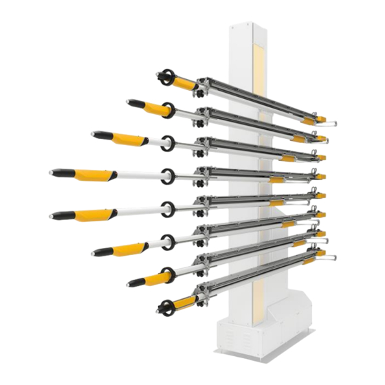
The axis is mounted on the ZA16 vertical axis only. The maximum load of the vertical axis is approx. 130 kg – Mount a maximum of 8 gun axes type UA05, either on one side or on both sides. Fig. 8: UA05 mounted on ZA16 (left / right) Fig. -
Page 27: Grounding Of The Axis
10: Potential equalization – connection point Electrical/pneumatic connections and cable connections The electrical and pneumatic installations are to be done as indicated in the attached diagrams. Caution - damage to the components! Assembly / Connection • 27 UA05... - Page 28 Rev. 00 09/22 28 • Assembly / Connection UA05...
-
Page 29: Start-Up
The stroke length of the axis must be in the range of the booth opening (collision danger!) – Make sure that the automatic guns cannot collide with the work pieces (incorrectly adjusted stroke parameters on the axis control unit) Start-up • 29 UA05... -
Page 30: Reference Point
ATTENTION Damages to the booth, to the gun holders etc. Reference point incorrectly set ► Check the reference point before the first start-up and if necessary, reset! ► Fit the mechanical stop to the gun slots! 30 • Start-up UA05... -
Page 31: Setting Of The Mechanical Stop
Fig. 11: Reference point and mechanical stop Stop Fixing screws The position of the mechanical stop is set by a Gema service engineer during assembly. The reference point must be referenced before each start-up (at each switching on, after an interruption of the power supply etc.)! - Page 32 Rev. 00 09/22 32 • Start-up UA05...
-
Page 33: Operation
255 programs – change the program number – directly modify the running program – acknowledge the error message – input the system parameters – etc. For further information, see the corresponding operating manual! Operation • 33 UA05... - Page 34 Rev. 00 09/22 34 • Operation UA05...
-
Page 35: Decommissioning / Storage
If the physical conditions are maintained, the unit can be stored indefinitely. Space requirements The space requirements correspond to the sizes of the axes of motion. There are no special requirements concerning distance to neighboring equipment. Decommissioning / Storage • 35 UA05... -
Page 36: Physical Requirements
The linear guide unit running surface of the gun axis must be thoroughly cleaned. Preservation No preservation is necessary. Maintenance during storage Maintenance schedule No maintenance schedule is necessary. Maintenance works During long-term storage, periodically perform a visual check. 36 • Decommissioning / Storage UA05... -
Page 37: Maintenance / Repairs
The axis was designed to operate with a minimum of maintenance. The motor is self-lubricating and maintenance-free. Regular maintenance and inspection of the axis increases the working reliability and avoids damages, repair downtimes etc.! Maintenance / Repairs • 37 UA05... -
Page 38: Maintenance Schedule
During assembly, cleaning, maintenance and commissioning when close to live components, an electric shock can cause serious injury or death. ► All work must be carried out only by trained personnel and when no power is applied! 38 • Maintenance / Repairs UA05... -
Page 39: Replacing The Drive Unit
Remove the motor flange (2) with the motor Disconnect the motor cable from the clamp plate Loose and remove the safety screw (3) Remove the toothed belt wheel (4) 10. Loose the motor flange screws (5) Maintenance / Repairs • 39 UA05... -
Page 40: Toothed Belt
Switch on the gun axis and check the carriage for quiet running. Check the toothed belt for elongation or wear (noisy running, or similar) Replacing the toothed belt Procedure: Fig. 14: Toothed belt Switch off the power supply. Remove the protective cover 40 • Maintenance / Repairs UA05... -
Page 41: Replacing The Gliding Elements
If the carriage starts to vibrate excessively during operation, especially at the reversing points, in most cases the cause lies in too much play in the gliding elements! fig. 15: Material and tool required Procedure: Switch off the electric power Maintenance / Repairs • 41 UA05... - Page 42 Rev. 00 09/22 42 • Maintenance / Repairs UA05...
- Page 43 Rev. 00 09/22 Maintenance / Repairs • 43 UA05...
- Page 44 Rev. 00 09/22 The carriage should run evenly and quietly again! 44 • Maintenance / Repairs UA05...
-
Page 45: Setting The Support Roller
The position regulator does not require a preventive maintenance. However, it is recommended to carry out the following inspections by the user in regular intervals: – Check condition and tightness of the cable connections. Maintenance / Repairs • 45 UA05... -
Page 46: Replacing The Position Regulator
► After switching off the power supply, wait at least 10 min. before working on the equipment, because the internal condensers need this time for discharging! ► Verify that the parts are deenergized by means of a voltmeter! 46 • Maintenance / Repairs UA05... -
Page 47: Fault Clearance
During referencing, The system adjust the system parameter “Change the axis moves in parameter "Change the wrong direction direction of direction of movement” is set movement" (see axis incorrectly control operating manual) Fault clearance • 47 UA05... - Page 48 Gliding elements replace guiding worn elements (see chapter "Replacing the gliding elements") Squeaking noise Toothed belt scrapes check the toothed during operation against flange of belt, tension toothed wheel correctly, if necessary Align toothed wheel 48 • Fault clearance UA05...
-
Page 49: Disposal
Requirements on personnel carrying out the work The disposal of the product is to be carried out by the owner or operator. When disposing of components that are not manufactured by Gema, the instructions in the respective third-party manufacturer’s documentation must be observed. -
Page 50: Materials
Disconnect the mains supply, supply cables and additional units. Remove all product covers. Drain all existing lubricant supplies and dispose of accordingly. The product is now prepared for disassembly. The instructions in the third-party manufacturer’s documentation must be followed! 50 • Disposal UA05... -
Page 51: Spare Parts List
When using the spare parts from other manufacturers the explosion protection is no longer guaranteed. If any damage is caused by this use all warrantee claims become invalid! ► Only original Gema spare parts should be used! Spare parts list • 51 UA05... -
Page 52: Ua05 - Complete
Rev. 00 09/22 UA05 – complete In order to prevent incorrect delivery please clearly indicate the axis serial number – see Rating plate! UA05 – complete (see chapter "Technical Data" on page 20) Toothed belt 1014 825 Servo motor 1022 222... -
Page 53: Position Regulator
Position regulator UA (please indicate the axis serial number – see Rating plate) 1014 184 Motor cable (not shown) 1014 992 Pulse generator cable (not shown) 1014 993 * Please indicate length fig. 18: Position regulator Spare parts list • 53 UA05... - Page 55 Fault clearance ..........47 Storage ............35 Figure references in the text ......8 Technical Data ..........20 Maintenance ............. 37 Transport ............13 Maintenance during storage ......36 Mechanical data ..........20 Versions ............20 Spare parts list • 55 UA05...
- Page 56 Rev. 00...
Need help?
Do you have a question about the UA05 and is the answer not in the manual?
Questions and answers