
Related Manuals for Rockwell Automation Allen-Bradley PowerFlex 750 ATEX Series


Summary of Contents for Rockwell Automation Allen-Bradley PowerFlex 750 ATEX Series
- Page 1 PowerFlex 750-Series ATEX Option Module Catalog Number 20-750-ATEX User Manual Original Instructions...
- Page 2 If this equipment is used in a manner not specified by the manufacturer, the protection provided by the equipment may be impaired. In no event will Rockwell Automation, Inc. be responsible or liable for indirect or consequential damages resulting from the use or application of this equipment.
-
Page 3: Table Of Contents
PowerFlex 755/755T Integrated Safety Functions Option Module 30 Reset the Drive after an SSM Fault Detection....30 Rockwell Automation Publication 750-UM003G-EN-P - November 2022... - Page 4 ............45 Rockwell Automation Publication 750-UM003G-EN-P - November 2022...
-
Page 5: Preface
Throughout this manual, PowerFlex 755T drive products are used to refer to PowerFlex 755TL drives, PowerFlex 755TR drives, and PowerFlex 755TM drive systems. IMPORTANT Read and understand this user manual before you begin to design and install your ATEX system. Rockwell Automation Publication 750-UM003G-EN-P - November 2022... - Page 6 Preface Notes: Rockwell Automation Publication 750-UM003G-EN-P - November 2022...
-
Page 7: Safety Concepts
Certification of the drive for the ATEX group and category on its nameplate is based on installation, operation, and maintenance according to these items: • This user manual • The requirements in the drive user manual and installation instructions • The instruction manual for the motor Rockwell Automation Publication 750-UM003G-EN-P - November 2022... -
Page 8: Motor Requirements
• Typical motor markings are contained on a motor certification nameplate similar to the sample here. FLAMEPROOF Exd ENCLOSURE Exd I/IIB Tamb C to II 2 G/D 0035 I M2 Sira ATEX MFG. BY ROCKWELL AUTOMATION Rockwell Automation Publication 750-UM003G-EN-P - November 2022... -
Page 9: About The Powerflex 750-Series Atex Option Module
A drive that is installed in a potentially explosive atmosphere can cause an explosion. (1) Throughout this manual, the PowerFlex 755TL low harmonic drives, PowerFlex 755TR regenerative drives, and PowerFlex 755TM drive systems are also referred to as PowerFlex 755T drive products. Rockwell Automation Publication 750-UM003G-EN-P - November 2022... -
Page 10: Catalog Numbers For Spare Terminal Plugs
WARNING: Risk of Explosion. Do not install the PowerFlex 750-Series drive or PowerFlex 755T drive products in a potentially explosive atmosphere. A drive that is installed in a potentially explosive atmosphere can cause an explosion. Rockwell Automation Publication 750-UM003G-EN-P - November 2022... -
Page 11: Atex Function
The safe-off function initiates when the ATEX option module detects that the contact is open. This trip can be the result of a broken wire, or an over-temperature condition in the motor. Rockwell Automation Publication 750-UM003G-EN-P - November 2022... -
Page 12: Positive Temperature Coefficient (Ptc) Trip
EN 61800-5-2 and IEC 61508 Part 2. The overall ATEX function has a hardware fault tolerance of zero. IMPORTANT If one fault occurs in the safety path, the safety function can become compromised. Rockwell Automation Publication 750-UM003G-EN-P - November 2022... -
Page 13: Safety Reaction Time
If you experience a failure with any safety-certified device, contact your local Allen-Bradley distributor to do the following: Safety Option Failure • Return the device to Rockwell Automation so the failure is appropriately Occurs logged for the catalog number that is affected and a record is made of the failure. - Page 14 Chapter 1 Safety Concepts Notes: Rockwell Automation Publication 750-UM003G-EN-P - November 2022...
-
Page 15: Installation And Wiring
ATTENTION: The following information is a guide for proper installation. Rockwell Automation does not assume responsibility for the compliance or the noncompliance to any code, national, local, or otherwise, for the proper installation of this equipment. Personal injury and/or equipment damage can occur if codes are ignored during installation. -
Page 16: Perform A Safety Analysis Of The Motor
The option module is installed in the drive control pod. Different drives have different ways to access the control pod. To access the control pod, follow these steps. 1. Open the door or remove the cover. 2. Loosen the retention screw on the HIM cradle. Rockwell Automation Publication 750-UM003G-EN-P - November 2022... - Page 17 Chapter 2 Installation and Wiring 3. Lift the cradle until the latch engages. Panel-mounted Drives Drives in Cabinet Enclosures See the installation instructions for your drive for more information. Rockwell Automation Publication 750-UM003G-EN-P - November 2022...
-
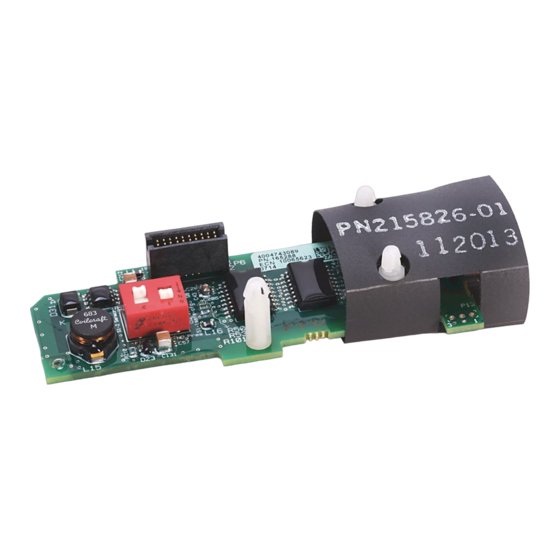
Page 18: Configure The Hardware
Figure 3 - ATEX Option Module S1 Switch Location In this diagram, the ATEX option module is S1-1 S1-2 shown without the insulation wrapper. Do not remove the insulation wrapper from the ATEX option module. Rockwell Automation Publication 750-UM003G-EN-P - November 2022... -
Page 19: Safety Enable Jumper Locations
IMPORTANT PowerFlex 755 floor mount Frame 8 drives and larger do not have a safety enable jumper. Figure 4 - Safety Enable Jumper Locations on the Main Control Board PowerFlex 753 Drive PowerFlex 755 Drive PowerFlex 755TS Drive PowerFlex 755T Drive Products Rockwell Automation Publication 750-UM003G-EN-P - November 2022... -
Page 20: Without A Safety Option Module
3. Install the safety enable jumper on the main control board. IMPORTANT The default setting of the safety enable jumper = installed. For this step, verify that the safety enable jumper is installed. Rockwell Automation Publication 750-UM003G-EN-P - November 2022... -
Page 21: With A Safety Option Module
To configure the ATEX option module with 11-Series I/O option module for use with one of these option modules, follow these steps. 1. Set switch S1-1 to OFF. 2. Set switch S1-2 for Thermostat mode or PTC mode. Rockwell Automation Publication 750-UM003G-EN-P - November 2022... - Page 22 IMPORTANT The default setting of the safety enable jumper = installed. For this step, verify that the safety enable jumper is removed. PowerFlex 755T Drive Products PowerFlex 753 Drive PowerFlex 755 Drive PowerFlex 755TS Drive Rockwell Automation Publication 750-UM003G-EN-P - November 2022...
-
Page 23: Assemble The Atex And 11-Series I/O Option Modules
11-Series I/O option module. Once the module is snapped into place, the switches are no longer accessible. 1. Align the stand-off pins and the 20-pin connector. 20-pin Connector Stand-off Pins Rockwell Automation Publication 750-UM003G-EN-P - November 2022... -
Page 24: Connect The Thermal Sensor Wires
Follow these requirements for thermal sensor wiring to the removable terminal block of the ATEX option module: • Use cable duct, conduit, armored cable, or other means to help protect the thermal sensor wires from damage. • Use shielded, twisted-pair cable. Rockwell Automation Publication 750-UM003G-EN-P - November 2022... -
Page 25: Installation Requirements
2. Route the thermal sensor wires that are attached to the ATEX removable terminal block under the lower mounting bracket. TIP Leave enough length in the cable so that you can remove the option module in the future, if needed. Rockwell Automation Publication 750-UM003G-EN-P - November 2022... - Page 26 4. Firmly press the 11-Series I/O option module edge connector into port 4 or port 5. IMPORTANT The ATEX option module that is mounted on an 11-Series I/O option module can be installed only in drive ports 4 or 5. PowerFlex 755 Drive Shown Rockwell Automation Publication 750-UM003G-EN-P - November 2022...
-
Page 27: Powerflex 750-Series Safe Torque Off Option Wiring
For information on setting the safety configuration switch, see ATEX Option Module and 11-Series I/O Option Module with a Safety Option Module on page 21 11-Series I/O Safe Torque Off Option Option Module, TB1 Module, TB2 Rockwell Automation Publication 750-UM003G-EN-P - November 2022... -
Page 28: Safe Speed Monitor Option Wiring
For information on setting the safety configuration switch, see ATEX Option Module and 11-Series I/O Safe Speed Monitor 11-Series I/O Option Module with a Safety Option Module on page 21 Option Module, TB1 Option Module, TB2 Rockwell Automation Publication 750-UM003G-EN-P - November 2022... -
Page 29: Integrated Safety - Safe Torque Off Option Module
See Verify Operation on page 31. IMPORTANT When a safety option is installed with the ATEX option, you must wire the EnC and EnNO dry contacts. Rockwell Automation Publication 750-UM003G-EN-P - November 2022... -
Page 30: Powerflex 755/755T Integrated Safety Functions Option Module
The ATEX option module with the 11-Series I/O option module can be used without a safety option with the safety signal on the backplane. The EnC and Option EnNO contacts can be left unwired. Rockwell Automation Publication 750-UM003G-EN-P - November 2022... -
Page 31: Description Of Functionality
ATEX motors with thermostat contacts or PTC-type devices. Functionality The module removes power from the gate firing circuits of the drive output power devices (IGBTs) when the temperature circuit in the motor indicates that the motor temperature is too high. Rockwell Automation Publication 750-UM003G-EN-P - November 2022... -
Page 32: Motors With Thermostatic Switches
See ATEX Fault Descriptions on page 4. If a safety option is present, check parameter 933 [Start Inhibits] and verify that bit 2 [Enabled] and bit 7 [Safety] are set to high. Rockwell Automation Publication 750-UM003G-EN-P - November 2022... -
Page 33: Motors With Positive Temperature Coefficient (Ptc) Devices
See ATEX Fault Descriptions on page 5. If a safety option is present, check parameter 933 [Start Inhibits] and verify that bit 2 [Enabled] and bit 7 [Safety] are set to high. Rockwell Automation Publication 750-UM003G-EN-P - November 2022... -
Page 34: Functional Proof Testing Without A Test Fixture
• PowerFlex 755TM IP00 Open Type Kits Installation Instructions, publication 750-IN101. 5. Unplug the ATEX terminal plug from the ATEX daughter board. 6. Power up the drive. If the ATEX safety function is operating correctly, an over temperature fault is enunciated. Rockwell Automation Publication 750-UM003G-EN-P - November 2022... - Page 35 10. Power up the drive and verify that the over temperature fault can now be cleared. If the SSM option is present, additional steps are required. See Reset the Drive after an SSM Fault Detection on page Rockwell Automation Publication 750-UM003G-EN-P - November 2022...
- Page 36 Chapter 3 Verify Operation Notes: Rockwell Automation Publication 750-UM003G-EN-P - November 2022...
-
Page 37: Parameter 41 [Atex Sts]
Bit 3 “Voltage Loss” – Voltage loss fault has taken place on ATEX board. Bit 13 “Thermostat” – Thermostat input has been selected. Bit 14 “PTC Selected” – PTC input has been selected. Rockwell Automation Publication 750-UM003G-EN-P - November 2022... -
Page 38: Atex Fault Descriptions
The ATEX option module and 11-Series I/O option module is installed in an unsupported port. X Port 06 ‘Safe Speed Montr’ The safety configuration switch (S1-1) is set to ‘ON’ , and a safety option is present. Rockwell Automation Publication 750-UM003G-EN-P - November 2022... -
Page 39: Restart The Drive After An Over-Temperature Fault
TIP For more information on faults and how to restart the drive, see the troubleshooting section in the manual for your drive: • PowerFlex 750-Series AC Drives Programming Manual, publication 750-PM001 • PowerFlex Drives with TotalFORCE Control Programming Manual, publication 750-PM100 Rockwell Automation Publication 750-UM003G-EN-P - November 2022... - Page 40 Chapter 4 ATEX Monitoring Notes: Rockwell Automation Publication 750-UM003G-EN-P - November 2022...
-
Page 41: General Specifications
6 (0.24) Tension clamp terminals 2.5 (14) 0.13 (26) N/A 10 (0.39) Screw terminals 4.0 (12) 0.25 (24) 0.5 (4.4) 0.4 (3.5) 7 (0.28) Tension clamp terminals 4.0 (12) 0.25 (24) N/A 10 (0.39) Rockwell Automation Publication 750-UM003G-EN-P - November 2022... -
Page 42: Safety Data
• PowerFlex 755TM IP00 Open Type Kits Technical Data, publication 750-TD101 Vibration Operating Packaged for shipment Sinusoidal load Random secured Surrounding environment ATTENTION: Failure to maintain the specified ambient temperature can result in a failure of the safety function. Rockwell Automation Publication 750-UM003G-EN-P - November 2022... -
Page 43: Certifications
Radiocommunications Labeling (EMC) Notice: 2008 IEC 61800-3 KCC (Korea) Radio Waves Act: Article 58-2 http://rok.auto/certifications (1) Certification information can be viewed at (2) Underwriters Laboratories Inc. has not evaluated the ATEX option module for functional safety. Rockwell Automation Publication 750-UM003G-EN-P - November 2022... - Page 44 Appendix A Specifications and Certifications Notes: Rockwell Automation Publication 750-UM003G-EN-P - November 2022...
-
Page 45: Index
19 X Port 06 38 safety enable installed 20 X Port 06 ‘Safe Speed Montr’ 38 safety enable removed 22 drive enclosure rating specifications 42 drive ports 26 dry contact 28 dust 7 Rockwell Automation Publication 750-UM003G-EN-P - October 2022... - Page 46 39 risk wiring assessment 15 safe speed monitor option module 28 of explosion 10 safe torque-off option module 27 thermal sensor 24 S1 switches S1-1 18 S1-2 18 safe state 12 Rockwell Automation Publication 750-UM003G-EN-P - October 2022...
- Page 47 PowerFlex 750-Series ATEX Option Module User Manual Additional Resources These documents contain additional information concerning related products from Rockwell Automation. Resource Description Provides the basic steps to install PowerFlex 755TL low PowerFlex 750-Series Products with TotalFORCE Control Installation Instructions, publication...
- Page 48 At the end of life, this equipment should be collected separately from any unsorted municipal waste. Rockwell Automation maintains current product environmental compliance information on its website at rok.auto/pec. Allen-Bradley, expanding human possibility, PowerFlex, TotalFORCE, and Rockwell Automation are trademarks of Rockwell Automation, Inc. EtherNet/IP is a trademark of ODVA, Inc.
Need help?
Do you have a question about the Allen-Bradley PowerFlex 750 ATEX Series and is the answer not in the manual?
Questions and answers