
Related Manuals for Federal Signal Corporation CAMSET56-AHD-NTSC2


Summary of Contents for Federal Signal Corporation CAMSET56-AHD-NTSC2
- Page 1 Mobile Camera Systems Installation and Operation Manual 25500793 Rev A0 0622 Printed in U.S.A. © Copyright 2022 Federal Signal Corporation...
- Page 2 A copy of this limited warranty can also be obtained by written request to Federal Signal Corporation, 2645 Federal Signal Drive, University Park, IL 60484, email to info@fedsig.com or call +1 708-534-3400.
-
Page 3: Table Of Contents
Contents Safety Messages ...................... 4 An Overview of the Mobile Camera Systems............6 Installing the Mobile Camera System ..............9 Connecting the Mobile Camera System ............... 26 Operating the Mobile Camera System ..............32 Getting Technical Support and Service ..............38 Product Specifications and Part Numbers............ -
Page 4: Safety Messages
Safety Messages Safety Messages Safety Messages to Installers of Federal Signal Mobile Camera Systems People’s lives depend on your proper installation of our products. It is important to read and follow all instructions shipped with this product. Listed below are some other important safety instructions and precautions you should follow: •... - Page 5 Safety Messages • If a vehicle seat is temporarily removed, verify with the vehicle manufacturer if the seat needs to be recalibrated for proper airbag deployment. • Do not open or service the camera element. There are no user-serviceable parts inside. Opening or servicing any component will void the component’s warranty.
-
Page 6: An Overview Of The Mobile Camera Systems
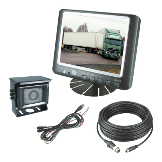
Turnkey Systems The following turnkey mobile camera systems are available: CAMSET56-AHD-NTSC2 CAMSET70-AHD-NTSC4 Each system includes a monitor, a standard rear-view camera, a camera-to-monitor extension cable, and accessories. - Page 7 An Overview of the Mobile Camera Systems • an input/power/trigger wiring harness with inputs and independent triggers for two cameras (CAMADP-INT-2) • a monitor mounting bracket with mounting hardware (CAMBRK-HD) Features: • Support for one or two cameras—an optional additional camera can connect to the CAM2 connector on the input/power/trigger wiring harness •...
- Page 8 An Overview of the Mobile Camera Systems • a four individual trigger wires for each of the available camera inputs • Input/power/trigger wiring harness with inputs and independent triggers for four cameras (CAMADP-INT-4) • Monitor mounting bracket with mounting hardware (CAMBRK-HD) Features: •...
-
Page 9: Installing The Mobile Camera System
Installing the Mobile Camera System • Ball camera (CAMAHD-BALLNTSC) Camera-to-monitor extension cables (one per camera) • 4 inches (0.1 m) (CAMCABLE-SHORT) • 16.5 feet (5 m) (CAMCABLE-5) • 33 feet (10 m) (CAMCABLE-10) • 49 feet (15 m) (CAMCABLE-15) • 65.5 feet (20 m) (CAMCABLE-20) •... - Page 10 Installing the Mobile Camera System electrical shorts, grommet all drilled holes through which wiring passes. (All Federal Signal camera systems include grommets.) Ensure that the mounting screws do not cause electrical or mechanical damage to the vehicle. • This camera is recommended for rear-view applications in heavy-duty vehicles.
-
Page 11: Figure 1 Rear-View Camera Installation
Installing the Mobile Camera System Figure 1 Rear-view camera installation (CAMAHD-REARNTSC) SUN SHIELD INSULATING VEHICLE CHASSIS FLAT WASHER LOCK WASHER 2 TO 4 SELF-TAPPING SCREWS WITH MOUNTING BRACKET PLASTIC INSULATORS, LOCK WASH- ERS, FLAT WASHERS AND NUTS 290A6046B Marking and Drilling the Mounting Holes for the Rear-View Camera AIRBAG DEPLOYMENT: Do not install equipment or route wiring in the deployment path of an airbag. - Page 12 Installing the Mobile Camera System LOCATING OPERATORS CONTROLS: Locate the camera(s) so the VEHICLE and SYSTEM can be operated safely under all driving conditions. Failure to heed this caution could result in driver distraction or driver error while operating the vehicle. To mark and drill the mounting holes: 1.
- Page 13 Installing the Mobile Camera System 3. Drill holes at the drill position marks that are correctly sized for the screws you are using: • If you are using the self-tapping screws, drill two to four 9/64-inch (3.5 mm) holes. • If you are using the machine screws, drill two to four 13/64-inch (5.2 mm) clearance holes.
- Page 14 Installing the Mobile Camera System 4. Connect one of these camera extension cables to the camera: • one CAMCABLE-SHORT/-5/-10/-15/-20 • one CAMCABLE-40 5. Wrap the cable connection in the supplied black waterproofing tape. Installing the Side-View Camera (CAMAHD-SIDENTSC) Before the installation, find an appropriate location for the side-view camera with these considerations in mind: •...
-
Page 15: Figure 2 Side-View Camera Installation
Installing the Mobile Camera System • If the camera is to be used in a typical side-view camera application, the camera should be positioned so that the driver can obtain a wide, unobstructed field of vision of the left or right side of the vehicle. Preparing to Install the Side-View Camera 1. - Page 16 Installing the Mobile Camera System To verify the orientation of the camera in its housing before the installation, connect the camera to the monitor and turn on the system. You can adjust the camera assembly inside the housing for either the left or right side of the vehicle. If the image on the monitor appears upside down on the preferred installation side of the vehicle, use the Allen wrench to...
- Page 17 Installing the Mobile Camera System • a camera extension cable that can be: ◦ one CAMCABLE-SHORT/-5/-10/-15/-20/-40 that is connected to: ◦ either the CAM1 or CAM2 input on the input/ power/trigger wiring harness (CAMADP-INT-2) of the CAMLCD-AHD-56 monitor or ◦ one of the four camera inputs on the input/power/ trigger wiring harness (CAMADP-INT-4) of the CAMLCD-AHD-70 DRILLING PRECAUTIONS: When drilling holes, check the area...
- Page 18 Installing the Mobile Camera System drilled holes. Fasten the screws tightly to the vehicle body. • If you are using the machine screws, guide each screw with a lock washer and flat washer through the camera base. Install the matching nut on the opposite side of the vehicle surface.
- Page 19 Installing the Mobile Camera System the ball camera on a side-view mirror assembly. The camera should be positioned so that the driver can obtain a wide, unobstructed field of vision. Preparing to Install the Ball Camera To prepare to install the camera: 1.
-
Page 20: Figure 3 Ball Camera Installation
Installing the Mobile Camera System Figure 3 Ball camera installation CAMAHD-BALLNTSC 290A6049 Marking and Drilling the Mounting Holes for the Ball Camera AIRBAG DEPLOYMENT: Do not install equipment or route wiring in the deployment path of an airbag. Failure to observe this warning will reduce the effectiveness of the airbag or potentially dislodge the equipment, causing serious injury. - Page 21 Installing the Mobile Camera System To mark and drill the mounting holes: 1. Use the bottom half of the camera mounting bracket as a guide to mark the locations of the two mounting holes on the vehicle chassis. 2. Mark a location nearby for the 3/4-inch (19.0 mm) hole for the camera output cable.
- Page 22 Installing the Mobile Camera System 4. Drill a 3/4-inch (19.0 mm) hole at the mark for the camera output cable. Smooth and deburr the hole. Mounting the Ball Camera To mount the camera: 1. Align the bottom half of the camera mounting bracket with the drilled mounting holes on the vehicle while inserting the insulating pad between the vehicle surface and the camera mounting bracket.
- Page 23 Installing the Mobile Camera System Installing the Monitor (CAMLCD-AHD-56, CAMLCD-AHD-70) Before the installation, find an appropriate location for the monitor with these considerations in mind: • The location should be able to support 9 pounds (4 kg) and should not obstruct the view of the driver. •...
-
Page 24: Figure 4 Camlcd-Bracket Mounting Bracket And Hardware
Installing the Mobile Camera System SEAT REMOVAL PRECAUTION: If a vehicle seat is temporarily removed, verify with the vehicle manufacturer if the seat needs to be recalibrated for proper airbag deployment. Failure to heed this warning could result in death or serious injury. LOCATING OPERATORS CONTROLS: Locate the camera(s) so the VEHICLE and SYSTEM can be operated safely under all driving conditions. -
Page 25: Figure 5 Cambrk-Hd Mounting Bracket And Hardware
Installing the Mobile Camera System Figure 5 CAMBRK-HD mounting bracket and hardware DRILLING PRECAUTIONS: When drilling holes, check the area into which you are drilling to ensure that you do not damage vehicle components while drilling. All drilled holes should be deburred, and all sharp edges should be smoothed. -
Page 26: Connecting The Mobile Camera System
This section describes how to connect two Mobile Camera System configurations: • Option 1: System configured with a CAMLCD-AHD-56 monitor (as in the CAMSET56-AHD-NTSC2). System configured with a CAMLCD-AHD-56 monitor (as in the CAMSET56-AHD-NTSC2) • Option 2: Option 2: System configured with a CAMLCD-... - Page 27 Connecting the Mobile Camera System • White (White/CAM2): Connect a 12-24 V signal to this wire to trigger when the monitor should display CAM2. The green (CAM1) wire trigger will override a trigger from this wire. • CAM1 and CAM2: Connect cameras to these inputs. A CAMCABLE-SHORT/-5/-10/-15/-20/-40 connected to one of these inputs can provide camera cable extension up to 131 ft (40 m).
-
Page 28: Figure 6 System Configured With A Camlcd-Ahd-56 Monitor
Connecting the Mobile Camera System Figure 6 System configured with a CAMLCD-AHD-56 monitor CAMCCD #1 CAMCCD #2 CAMCABLE-SHORT/-5/-10/-15/-20/-40 /CAM SEL MENU MODE/ON MONITOR (CAMLCD-INT-56) CAM1 CAM2 INPUT INPUT CAMADP-INT-2 CAM1 TRIGGER (GREEN/REVERSE) CAM2 TRIGGER (WHITE/CAM2) GROUND (BLK/GND) 290A6300C +12/24VDC (RED/DC INPUT) Mobile Camera System Federal Signal www.fedsig.com... - Page 29 Connecting the Mobile Camera System Option 2: System configured with CAMLCD-AHD-70 monitor, as in the CAMSET70-AHD-NTSC4 An example system is shown in Figure 8. 1. Connect the 26-pin male connector on the monitor to the 26-pin female connector on the CAMADP-INT-4 input/ power/trigger wiring harness.
-
Page 30: Figure 7 System Configured With A Camlcd-Ahd-70 Monitor
Connecting the Mobile Camera System Figure 7 System configured with a CAMLCD-AHD-70 monitor Mobile Camera System Federal Signal www.fedsig.com... - Page 31 Connecting the Mobile Camera System Testing the System After the installation, test the emergency warning system to ensure that it is operating properly. Also test all vehicle functions, including horn operation, vehicle safety functions, and vehicle lighting systems to ensure proper operation. Ensure that the installation has not affected the vehicle operation or changed any vehicle safety functions or circuits.
-
Page 32: Operating The Mobile Camera System
This section describes how to operate these Mobile Camera System configurations: • Option 1: System configured with a CAMLCD-AHD-56 monitor (as in the CAMSET56-AHD-NTSC2) monitor. System configured with a CAMLCD-AHD-56 monitor (as in the CAMSET56-AHD-NTSC2) • Option 2: System configured with a CAMLCD-AHD-70... -
Page 33: Figure 8 Camlcd-Ahd-56
Operating the Mobile Camera System trigger wire. When you turn on the system or switch between cameras, CAM1 or CAM2 appears for approximately four seconds to show which camera is being viewed. To return the system to Standby Mode, press and hold CAM/SEL. - Page 34 (mirror or normal) is recalled when you turn on the system. NOTE: The MIR/NOR button is available only on the CAMSET56-AHD-NTSC2 system. Option 2: System Configured with a CAMLCD-AHD-70 monitor (as in CAMSET70-AHD-NTSC4) When you turn on the camera system by turning the vehicle ignition key to either the “Accessory”...
-
Page 35: Figure 9 Camlcd-Ahd-70
Operating the Mobile Camera System Figure 9 CAMLCD-AHD-70 / CAM SEL MENU MODE/D/N 290A6053B POWER INDICATOR LED Screen Configurations • If one camera is connected, its image is displayed full screen. • If two cameras are connected, one camera is displayed on the top half of the screen and the other on the bottom half in a split-screen. - Page 36 Operating the Mobile Camera System SEL (power/camera select) button select a different pair of the images of the connected camera (CAM1/CAM2, CAM2/CAM3, etc.). • Press Mode/D/N a third time to return to a split-screen image of all connected cameras. Automatic Camera Triggering Automatic triggering of connected cameras is supported as follows: •...
- Page 37 Operating the Mobile Camera System • Color: Adjusts the amount of color information in the monitor image on a scale of 0 to 30. • Volume: Adjusts the volume of the sound from the selected camera microphone on a scale of 0 to 30, as applicable.
-
Page 38: Getting Technical Support And Service
Getting Technical Support and Service Getting Technical Support and Service For technical support and service, please contact: Service Department Federal Signal Corporation Phone: 1-800-433-9132 Email: empserviceinfo@fedsig.com www.fedsig.com Getting Repair Service The Federal Signal factory provides technical assistance with any problems that cannot be handled locally. -
Page 39: Product Specifications And Part Numbers
Product Specifications and Part Numbers Product Specifications and Part Numbers This section has specifications for each model of camera. Camera Specifications Table 1 CAMAHD-REARNTSC: Rear-View Camera Imaging sensor Sony 1/3" CMOS Resolution in pixels 1280 x 960 (H x V) Lens Focal length 2.6 mm, F2.0, 118°... -
Page 40: Table 2 Side-View Camera
Product Specifications and Part Numbers Table 2 CAMAHD-SIDENTSC: Side-View Camera Imaging sensor Sony 1/3" CMOS Resolution in pixels 1280 x 960 (H x V) Lens Focal length 2.6 mm, 2.8 mm, 124° viewing angle (measured diagonally) Low-light/night vision Nine infrared LEDs with photosensor Microphone Integrated Camera housing... -
Page 41: Table 3 Ball Camera
Product Specifications and Part Numbers Table 3 CAMAHD-BALLNTSC: Ball Camera Imaging sensor Sony 1/3" CMOS Resolution in pixels 1280 X 960 (H x V) Lens 3.0 mm, F2.0, 118° viewing angle (measured diagonally) Low-light/night vision Nine infrared LEDs with photosensor Microphone Integrated Camera housing... -
Page 42: Table 4 5.6-Inch Monitor W/ Dual Integrated Camera Inputs
Product Specifications and Part Numbers Monitor Specifications Table 4 CAMLCD-AHD-56: 5.6-inch monitor w/ dual integrated camera inputs Screen type, size Color AHD LCD, 5.6 in (diagonal) Viewing angle (up/ 40°/50°, 60°/70° down, left/right) Brightness 200 cd/m2 Resolution in pixels 307200 (H x V) Camera inputs &... -
Page 43: Table 5 7.0-Inch Monitor W/ Four Integrated Camera Inputs
Product Specifications and Part Numbers Table 5 CAMLCD-AHD-70: 7.0-inch monitor w/ four integrated camera inputs Screen type, size Color AHD LCD, 7.0 in (diagonal) Viewing angle (up/ 60°/70°, 80°/80° down, left/right) Brightness 350 cd/m2 Resolution (pixels) 614400 Camera inputs & trigger wires Split-screen capable Built-in speaker... - Page 44 Product Specifications and Part Numbers Cables • CAMCABLE-40: 131 ft (40 m) camera extension cable with waterproof connector • CAMCABLE-20: 65.5 ft (20 m) camera extension cable with waterproof connector • CAMCABLE-15: 49 ft (15 m) camera extension cable with waterproof connector •...
- Page 45 Product Specifications and Part Numbers Adapters • CAMADP-RCA-IN: Adapter for connecting video/audio input from an external RCA-connector-equipped source to monitor • 4-pin DIN screw-type (male) to three male RCA connectors (yellow, white, and red) • CAMADP-RCA-OUT: adapter for connecting Federal Signal camera to external RCA-connector-equipped input •...
- Page 46 Product Specifications and Part Numbers FCC Compliance Statement For part numbers: For the following part numbers—CAMAHD-REARNTSC, CAMAHD-SIDENTSC, CAMAHD-BALLNTSC, CAMLCD- AHD-56, and CAMLCD-AHD-70: This device complies with part 15 of the FCC Rules. Operation is subject to the following two conditions: (1) This device may not cause harmful interference, and (2) this device must accept any interference received, including interference that may cause undesired operation.
- Page 47 2645 Federal Signal Drive University Park, Illinois 60484 www.fedsig.com Customer Support Police/Fire-EMS: 800-264-3578 • +1 708 534-3400 Work Truck: 800-824-0254 • +1 708 534-3400 Technical Support 800-433-9132 • +1 708 534-3400...
- Page 48 2645 Federal Signal Drive University Park, Illinois 60484 www.fedsig.com Customer Support Police/Fire-EMS: 800-264-3578 • +1 708 534-3400 Work Truck: 800-824-0254 • +1 708 534-3400 Technical Support 800-433-9132 • +1 708 534-3400...
Need help?
Do you have a question about the CAMSET56-AHD-NTSC2 and is the answer not in the manual?
Questions and answers