
Related Manuals for Federal Signal Corporation HighLighter


Summary of Contents for Federal Signal Corporation HighLighter
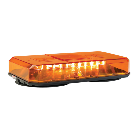
- Page 1 ™ LED Mini-Lightbars igHter Installation and Programming 2562495C REV. C 811 Printed in U.S.A.
- Page 2 Federal Signal Corporation. igHter FAStON is a registered trademark of Tyco Electronics AMP Corp. © 2011 Federal Signal Corporation...
-
Page 3: Table Of Contents
Contents Safety Message to Installers and Service Personnel of Warning Light Equipment .....5 Safety Message to Operators of Warning Light Equipment ................7 Introduction ............................9 Unpacking the Product ........................9 Product Specifications........................9 Permanently Mounting the H LED on the Vehicle ............10 igHter Preparing the Mounting Surface ........................10 Wiring the H LED ...................... - Page 4 ™ LED Mini-Lightbars igHter Figures Figure 1 Mounting holes for Patterns A and B ................... 11 Figure 2 Upper assembly removed from lightbar base ................12 Figure 3 Fuses, connectors, and programming jumper pins (PROG) ............13 Figure 4 Hole for Hall-effect sensor on PCB .....................17...
-
Page 5: Safety Message To Installers And Service Personnel Of Warning Light Equipment
™ LED Mini-Lightbars igHter Safety Message to Installers and Service Personnel of Warning Light Equipment People’s lives depend on your proper installation and servicing of Federal Signal products. It is important to read and follow all instructions shipped with this product. In addition, listed below are some other important safety instructions and precautions you should follow: NOTE: The term “vehicle”... - Page 6 ™ LED Mini-Lightbars igHter • The lighting system components, especially light bulbs, strobe tubes, LEDs, and the outer housing, get hot during operation. Be sure to disconnect power to the system and allow the system to cool down before handling any components of the system. •...
-
Page 7: Safety Message To Operators Of Warning Light Equipment
™ LED Mini-Lightbars igHter • If a vehicle seat is temporarily removed, verify with the vehicle manufacturer if the seat needs to be recalibrated for proper airbag deployment. • Locate the light system controls so the VEHICLE and CONTROLS can be operated safely under all driving conditions. - Page 8 ™ LED Mini-Lightbars igHter • All effective sirens and horns produce loud sounds which may cause, in certain situations permanent hearing loss. You and your passengers should consider taking appropriate safety precautions such as wearing hearing protection. • In order to be an effective warning device, this product produces bright light that can be hazardous to your eyesight when viewed at a close range.
-
Page 9: Introduction
™ LED Mini-Lightbars igHter Introduction This manual provides instructions for the installation, wiring, and maintenance of the H igHter Mini-Lightbar. The H LED is a high-performance warning light with a small outline and low igHter current draw. The H LED is designed to control or be controlled as part of a greater lighting igHter system. -
Page 10: Permanently Mounting The H Igh L Ighter Led On The Vehicle
™ LED Mini-Lightbars igHter Permanently Mounting the H LED on the Vehicle igHter AIRBAG DEPLOYMENT Do not install equipment or route wiring in the deployment of an airbag. Failure to observe this warning will reduce the effectiveness of the airbag or potentially dislodge the equipment, causing serious injury. -
Page 11: Wiring The H Igh Lled Ighter Lleded
™ LED Mini-Lightbars igHter Figure 1 Mounting holes for Patterns A and B NOTCH A 12.75" TO REAR B 12.05" OF VEHICLE 4.0" 5.21" KNOCKOUT FOR ADDITIONAL WIRING EXIT FOR WIRING LOCATIONS OF FUSES, CONNECTORS, AND JUMPER PIN ON PCB WITHIN THE HOUSING 290A6029B Select the mounting-hole pattern most appropriate for your installation and scribe four drill position marks on the mounting surface. -
Page 12: Completing The Wiring
™ LED Mini-Lightbars igHter Crimp 1/4-inch FASTON receptacles to the positive and ground wires. ® Figure 2 Upper assembly removed from lightbar base 1/4" HEX-HEAD SCREW (4) UPPER ASSEMBLY: INCLUDES DOME, PCB, AND REFLECTOR LIGHTBAR BASE 290A6617 Completing the Wiring Insert the grommet into the wire-routing hole and route the wires through the hole. -
Page 13: Completing The Installation Directly To The Vehicle
™ LED Mini-Lightbars igHter MAKE A GOOD GROUND CONNECTION The lightbar will not function properly without a good ground connection. Ensure that the black wire is attached to good vehicle ground. Route the wires or the optional cable kit from the control head or switch to the lightbar wires. Connect the black ground wire to ground. -
Page 14: Using Magnetic Or Magnetic/Suction Mounting
™ LED Mini-Lightbars igHter Using Magnetic or Magnetic/Suction Mounting DO NOT DRIVE WITH MAGNETICALLY-MOUNTED WARNING LIGHT INSTALLED Because vehicle roof construction and driving conditions vary, do not drive a vehicle with a magnetically mounted warning light installed. The light could fly off the vehicle causing injury or damage. -
Page 15: Table 2 Flash Patterns For Standard 12 V H Igh L Ighter Models
™ LED Mini-Lightbars igHter Table 2 Flash patterns for standard 12 V H models igHter Amber Pattern SAE J845 Number Description Class*** Alternating Quad Flash Full Quad Flash – 80 Quad Flashes per Minute Continuous Flash – 75 ms On, 75 ms Off Alternate Double Flash –... -
Page 16: Selecting A Pattern Using The Jumper Pins
™ LED Mini-Lightbars igHter Table 3 CAC Title 13 flash patterns for amber models Pattern Rate Number Description (FPM) Quad Flash with long fourth flash Quad Flash Front and Rear-Sides Quad Flash Double Flash Rotating Lightning Flash Triple Flash The “L” Seven Flash Strobe NFPA Flash #1 NFPA Flash #2... -
Page 17: Selecting A Pattern Using A Magnet Over The Hall-Effect Sensor
™ LED Mini-Lightbars igHter Selecting a Pattern Using a Magnet Over the Hall-Effect Sensor NOTE: A sufficiently strong magnet is needed to change patterns. A typical retrieval tool should have enough strength. A refrigerator magnet will most likely not have the required strength. Locate the programming sensor zone shown in Figure 4. -
Page 18: Ordering Replacement Parts
7 a.m. to 5 p.m., Monday through Friday (CT) Getting Technical Support and Service Federal Signal can service the lightbar for you. If you are experiencing problems, please contact: Service Department Federal Signal Corporation Phone: 1-800-433-9132 Fax: 1-800-343-9706 Email: empserviceinfo@fedsig.com... - Page 19 ™ LED Mini-Lightbars igHter Federal Signal Corporation Public Safety Systems 2645 Federal Signal Drive University Park, IL 60484-3167 Attn: Service Department RMA: #__________ 800-433-9132 800-343-9706 (fax) www.fedsig.com...
- Page 20 2645 Federal Signal Drive, University Park, IL 60466-3195 Tel.: (800) 264-3578 • Fax: (800) 682-8022 www.fedsig.com...
Need help?
Do you have a question about the HighLighter and is the answer not in the manual?
Questions and answers