
Related Manuals for Federal Signal Corporation JetSolaris JLX Series


Summary of Contents for Federal Signal Corporation JetSolaris JLX Series
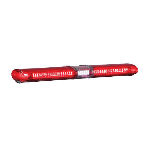
- Page 1 LED J ® Lightbar olariS with ROC™ Technology JLX 48”, 54”, 60”, and 72” Series Installation and Service Manual 2562335D REV. D 1112 Printed in U.S.A.
-
Page 3: Table Of Contents
Contents Chapter 1: Safety Messages ..................5 Safety Messages to Installers and Service Personnel of Warning Light Equipment ....5 Safety Message to Operators of Warning Light Equipment ..........8 Chapter 2: An Overview of the JLX JetSolaris ............. 10 Lightbar Specifications ....................10 Unpacking the Product ....................11 Before You Begin .......................11... - Page 4 Contents Figures Figure 3.1: Location (circles) of screws securing end dome ..........16 Figure 3.2: Location (circle) of S1 PROGRAM button ............17 Figure 4.1: SignalMaster control head ................20 Figure 4.2: Connections for SignalMaster control head ............22 Figure 5.1: Halogen worklight and takedown replacement types ..........25 Figure 5.2: Alley lamp replacement PN 8107241 ..............26 Figure 5.3: Adjustment screw for aiming the halogen lamp ..........27 Figure 5.4: Center board and end board exploded view............28...
-
Page 5: Chapter 1: Safety Messages
Chapter 1: Safety Messages For your safety, read this manual thoroughly before installing, operating, and servicing the Legend lightbar. The safety messages presented in this chapter and throughout the manual ® are reminders to exercise extreme care at all times. To download copies of the manual, go to www.fedsig.com or call the Federal Signal Service Department at 1-800-433-9132, 7 to 5 Monday through Friday (CT). - Page 6 Chapter 1: Safety Message to Installers and Service Personnel off. After disconnecting power to the unit, wait five minutes before handling any parts of the strobe system. • A light system is a high current system. In order for the system to function properly, a separate negative (–) connection and positive (+) connection must be made.
- Page 7 Chapter 1: Safety Message to Installers and Service Personnel • When drilling into a vehicle structure, be sure that both sides of the surface are clear of anything that could be damaged. Remove all burrs from drilled holes. To prevent electrical shorts, grommet all drilled holes through which wiring passes.
-
Page 8: Safety Message To Operators Of Warning Light Equipment
Chapter 1: Safety Message to Installers and Service Personnel Safety Message to Operators of Warning Light Equipment People’s lives depend on your safe use of our products. Listed below are some important safety instructions and precautions you should follow: • Do not attempt to activate or de-activate the light system control while driving in a hazard- ous situation. - Page 9 Chapter 1: Safety Message to Installers and Service Personnel A magnet mounting system should not be used on vehicles with vinyl tops. ✓ To prevent sliding of light assembly on mounting surface, quick acceleration and hard ✓ stops should be avoided. Failure to follow all safety precautions and instructions may result in property damage, serious injury, or death.
-
Page 10: Chapter 2: An Overview Of The Jlx Jetsolaris
Chapter 2: An Overview of the JLX JetSolaris The J is an LED lightbar that can be used in a variety of applications for Fire/Rescue, ® olariS Police, DOT, and Tow/Recovery. The J features the latest in S LED and ROC ®... -
Page 11: Unpacking The Product
Chapter 2: An Overview of the JLX JetSolaris Unpacking the Product After unpacking the product, examine it for damage that may have occurred in transit. If the product has been damaged, file a claim immediately with the carrier stating the extent of damage. -
Page 12: Chapter 3: Installing The Jlx J Et S Olaris
Chapter 3: Installing the JLX J olariS The lightbar is completely wired at the factory and does not require any additional internal wiring. All the conductors necessary to control the lightbar’s functions are contained in the cable. Installation of options requires additional wiring to the warning light system and vehicle battery. An installer-supplied switch or relay rated at 30 A is required for the connection between the JLX red power lead and the fused power source. -
Page 13: Control Wires For The Standard Jlx Lightbar
Chapter 3: Installing the JLX JetSolaris CURRENT CAPABILITY To provide safe operation of the lightbar, the power control switch and wiring must be capable of handling the rated current of the fuse at the source. HIGH CURRENT ARCING Do not connect this system to the vehicle battery until ALL other electrical connections are completed, mounting of all components are complete, and you have verified that no shorts exist. -
Page 14: Wiring The Controls For White Light And Front/Rear Cutoff
Chapter 3: Installing the JLX JetSolaris Table 3.1: 11-conductor cable wires (12 AWG) (Standard JLX) Wire Color Function Red* PRIMARY MODE: +12 Vdc: Activates the lightbar in Primary Mode. For a description of Primary Mode, see “Selecting Flash Patterns for Primary and Secondary Mode”... -
Page 15: Selecting Flash Patterns For Primary And Secondary Mode
Chapter 3: Installing the JLX JetSolaris Front or Rear Light Cutoff The lightbar may be equipped to shut off the front of the lightbar or the rear of the lightbar, while the rest of the lightbar is still flashing. The option is controlled by the green wire in the lightbar control cable. -
Page 16: Figure 3.1: Location (Circles) Of Screws Securing End Dome
Chapter 3: Installing the JLX JetSolaris Programming Secondary Mode To select a flash pattern for Secondary Mode: Apply +12 Vdc to both the Primary (red) and Secondary (blue) Mode wires to turn on the lightbar in Secondary Mode. Apply GND (–) to the orange wire in the lightbar cable. LIGHT HAZARDS To be an effective warning device, this product produces bright light that can be hazardous to your eyesight when viewed at a close range. -
Page 17: Figure 3.2: Location (Circle) Of S1 Program Button
Chapter 3: Installing the JLX JetSolaris Slide the end dome off the aluminum extrusion. Choose a mode to program: To select a pattern for in Primary Mode, apply +12 Vdc to the Primary (red) wire in the lightbar cable. To select a pattern for Secondary Mode, apply +12 Vdc to both the Primary (red) and Secondary (blue) Mode wires in the lightbar cable. -
Page 18: Table 3.2: Lightbar Flash Patterns For Standard Jlx Roc Lightbars
Chapter 3: Installing the JLX JetSolaris Table 3.2: Lightbar Flash Patterns for Standard JLX ROC Lightbars Pattern Description Pattern 1* 175 Alternating Single Pattern 2* Overlapping Penta Flash—87 FPM Pattern 3* Overlapping Alternating—95 FPM Pattern 4* Alternate Quad Flash—76 QFPM Pattern 5* Simultaneous/Overlapping Triple/Nine Pattern 6... -
Page 19: Operating In Dim Mode
Chapter 3: Installing the JLX JetSolaris Table 3.2: Lightbar Flash Patterns for Standard JLX ROC Lightbars (continued) Pattern 35 Double Flash Driver and Passenger Front Wraparound In-Out Followed by Double Flash of Driver and Passenger Rear Wraparound Out-In Pattern 36 Wraparound In-Out, Alt Double Flash, Wraparound Out-In, Full Quad Flash Pattern 37 Full Quad Flash, Wraparound Out-In, Alt Double Flash, Wraparound In-Out... -
Page 20: Chapter 4: Installing The Signalmaster (Option)
Chapter 4: Installing the SignalMaster (Option) The SignalMaster option includes a control head with a cable that has five 22 AWG leads and one 18 AWG jumper wire. If additional wire length is need, splice wire of the same gauge or heavier to the leads. -
Page 21: Wiring The Control Head
Chapter 4: Installing the SignalMaster (Option) Use the control head as a template and scribe two drill position marks at the selected mounting location. DRILLING PRECAUTIONS Before drilling holes, check the area into which you plan to drill to ensure you do not damage vehicle components while drilling. -
Page 22: Operating The Control Head
Chapter 4: Installing the SignalMaster (Option) SWITCH BRACKET HAZARD REAR VIEW SWITCH CHASSIS GROUND OFF-ON BROWN SWITCH WHITE GOLD TERMINAL BLACK GREEN JUMPER WIRE FROM INSTALLATION KIT NOTE: TWO WIRES ARE CRIMPED IN ONE TERMINAL CONTROL CABLE ASSEMBLY NOTE: MATING FEMALE TERMINALS ARE CRIMPED ON WIRES BEFORE CONNECTING TO SWITCHES. -
Page 23: Chapter 5: Servicing The Lightbar
Chapter 5: Servicing the Lightbar QUALIFICATIONS To properly service a lightbar, you must have a good understanding of automotive electrical procedures and systems along with proficiency in the installation and use of safety warning equipment. Establishing a regular maintenance schedule for the LED JlX extends the life of the lightbar and ensures safety. -
Page 24: Cleaning The Reflectors
Chapter 5: Servicing the Lightbar Cleaning the Reflectors Use a large flat-head screwdriver to remove the two 1/4-20 screws that secure the end dome to the aluminum extrusion (Figure 3.1 on page 16) and remove the nameplate. Slide the end dome off the aluminum extrusion along with any additional domes to access the PCB containing the reflectors. -
Page 25: Figure 5.1: Halogen Worklight And Takedown Replacement Types
Chapter 5: Servicing the Lightbar STATIC SENSITIVE DEVICE The PCBs can be damaged by an electrostatic discharge (ESD). Follow anti-static procedures while servicing the PCB. Replacing the Worklight and Takedown Halogen Lamps Depending on your lightbar configuration, the lightbar may be equipped with either type of lamp shown in Figure 5.1 below. -
Page 26: Figure 5.2: Alley Lamp Replacement Pn 8107241
Chapter 5: Servicing the Lightbar Replacing the Alley Lamps Disconnect power to the lightbar. Access the PCB containing the alley lamp: Use a large flat-head screwdriver to remove the two 1/4-20 screws that secure the end dome to the aluminum extrusion and remove the nameplate (Figure 3.1 on page 16). -
Page 27: Aiming The Halogen Lamps
Chapter 5: Servicing the Lightbar Aiming the Halogen Lamps You can adjust the aim of the halogen lamps horizontally +/– 8 degrees and vertically +2 degrees/–5 degrees. STATIC SENSITIVE DEVICE The PCBs can be damaged by an electrostatic discharge (ESD). Follow anti-static procedures while servicing the PCB. -
Page 28: Replacing An End Board
Chapter 5: Servicing the Lightbar Replacing an End Board If the LEDs and halogen lamps on the end board do not light, the fuse at F3 or F3 on the control board is intact, and you have replaced the lamps, the problem may lie with the end board or the control board. -
Page 29: Replacing The Control Board
Chapter 5: Servicing the Lightbar Use a 5/16" nut driver to remove the nut securing the ground connection to the aluminum extrusion. Remove the ring terminal from the ground stud. Remove the #8-32 Phillips screw securing the ground wire (GND) to the end PCB and remove the wire from the board. -
Page 30: Figure 5.5: Control Board Removed From Bracket
Chapter 5: Servicing the Lightbar 5/16" HEX HEAD SCREWS (10) SECURING THE END BRACKET TO THE ALUMINUM EXTRUSION END BRACKET (WITHOUT THE END PCB) CONTROL BOARD #6 PHILLIPS SCREWS (6) 290A6259 SECURING THE CONTROL BOARD TO THE BRACKET Figure 5.5: Control board removed from bracket Turn the bracket over to expose the control board. -
Page 31: Replacing A Fuse
Chapter 5: Servicing the Lightbar Secure the end bracket to the aluminum extrusion with the ten 5/16" screws. Install the end PCB and end dome as described in "Installing an End Board" on page 29. Reconnect power to the lightbar. Replacing a Fuse The control board, which is beneath the passenger-side PCB, has two 15 A automotive mini- blade fuses to protect the lightbar. -
Page 32: Replacing A Center Board
Chapter 5: Servicing the Lightbar Replacing a Center Board The center board is approximately one third the size of an end board. The 54" JLX has one center board, the 60" JLX has three, and the 72" JLX has four. If the LEDs and halogen lamps on the center board do not light, the fuse at F3 or F3 on the control board is intact, and you have replaced the lamps, the problem may lie with the center board. -
Page 33: Chapter 6: Ordering Parts And Service
Chapter 6: Ordering Parts and Service Federal Signal Corporation will service your equipment or provide technical assistance with any problems that cannot be handled locally. Contact your local dealer/distributor for replacement parts availability or contact the Federal Signal Service Department (7 a.m. to 5 p.m., Monday... - Page 34 Send all material with the issued RMA Number to: Federal Signal Corporation 2645 Federal Signal Drive University Park, IL 60484-3167 Attn: Service Department RMA: #__________ 2645 Federal Signal Drive, University Park, IL 60484-3167 Tel.: (800) 264-3578 • Fax: (800) 682-8022 www.fedsig.com © 2012 Federal Signal Corporation...
Need help?
Do you have a question about the JetSolaris JLX Series and is the answer not in the manual?
Questions and answers